6 common step motor mistakes to avoid in automation applications

6 common step motor mistakes to avoid in automation applications

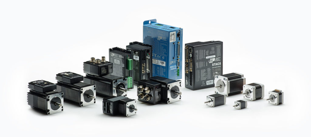
Step motors and drives from Applied Motion Products

The mistakes outlined here by Eric Rice, national marketing director at Applied Motion Products, have been corrected countless times by thousands of step motor users around the world. Avoid these mistakes with the presented solutions — and make your next application a successful one.

Step motors offer the automation industry a cost-effective and simple method to digitally control motion in a wide range of applications — including packaging equipment, 3D printers, material handling and sorting lines, bench-top CNC machines, and more. They serve as critical components of many rotary and linear positioning axes.

The cost-performance benefits of step motors lie in their simplicity and their ability to position accurately in open-loop control schemes, without any feedback from the motor to the controller. Getting the optimal performance benefits of an open-loop stepper system requires understanding how to specify and install a step motor into an application. Following are six common mistakes that step motor users, both novice and experienced, can easily avoid.

1. ‘The torque spec of the motor is higher than what I’m seeing in practice.’

After calculating the torque required to move the load in an application, a user selects a step motor based on (1) the holding torque specification of the motor or (2) the speed-torque curve. Once mounted and coupled to the load, the motor doesn’t produce the amount of expected torque.

The first mistake is using the holding torque as a measure of performance to specify the step motor. Holding torque defines the torque a motor produces when maintaining a position and not moving. It is generally a poor indicator of the torque the motor produces when moving.

When a step motor starts moving, the produced torque falls precipitously from the holding torque value, even after just a few rpms. As speed increases, the torque falls further. For this reason, don’t select a motor based on holding torque alone. Instead, refer to published speed-torque curves.

step motors from Applied Motion Products with various stack lengths

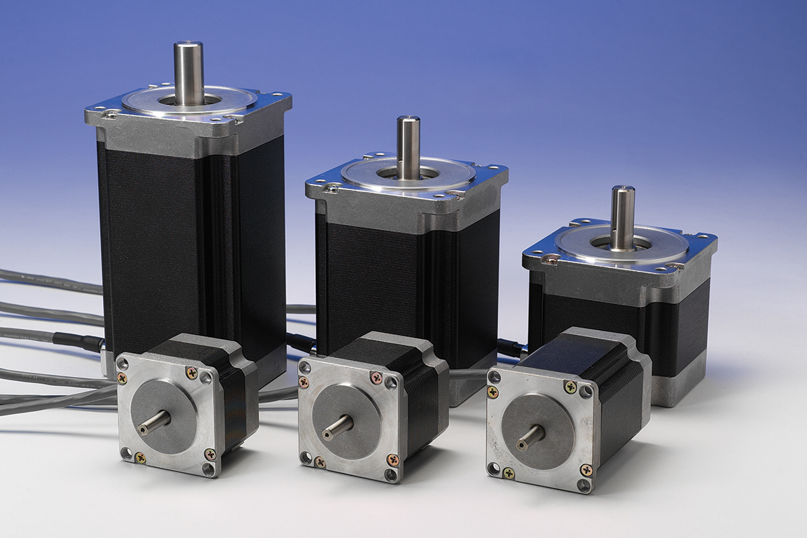
Shown here are step motors from Applied Motion Products with various stack lengths.

The second mistake is failing to understand the nature of speed-torque curves. A speed-torque curve represents the torque at which the step motor stalls. When a motor stalls, the rotor loses synchronization with the stator, and the shaft stops turning.

To ensure the step motor continues to turn and provides enough torque to move the load, evaluate the speed-torque curves by estimating a margin of safety. A simple way to do this is by imagining a line parallel to the speed-torque curve at roughly 1/2 to 2/3 the height of the published curve. This imaginary line represents an amount of torque that a step motor can reliably produce with minimal risk of stalling. See Figure 1 below for more on this.

typical speed-torque curve of a step motor

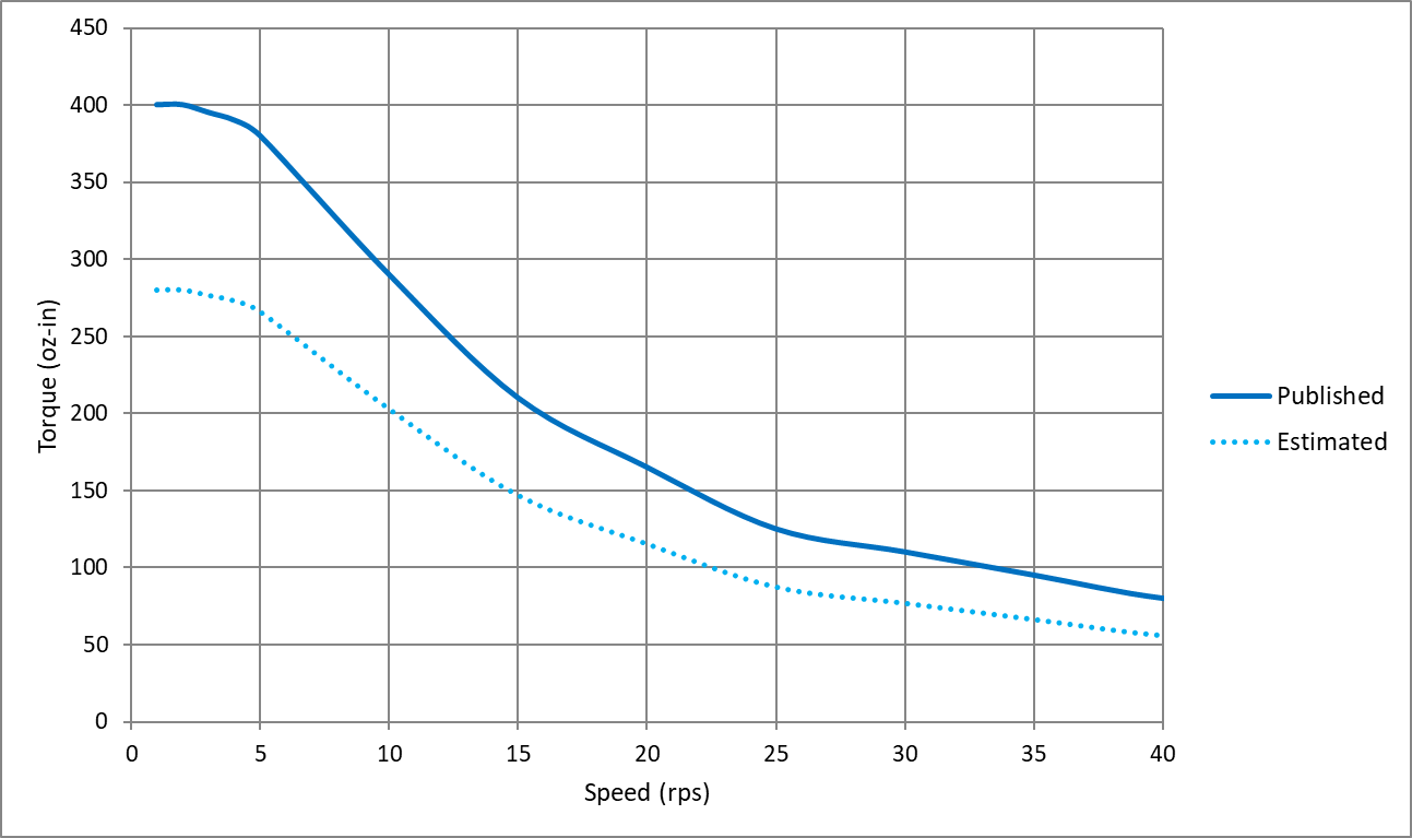
Figure 1 — typical speed-torque curve of a step motor. In published data from the manufacturer, only the solid line is shown, which indicates stall torque versus speed. The user must estimate a usable torque range as shown by the dashed line.

2. ‘The step motor is so hot; there must be something wrong with it.’

Step motors are designed to run hot. The most common insulation class used in step motors is Class B, which is rated for operation up to 130° C. This means that the surface temperature of a step motor can reach 90° C or more before failing. This temperature is much hotter than a person could touch without burning the skin. For this reason, mount motors away from areas with a high chance of human contact.

Step motors are designed to run at high temperatures because of their use in open-loop control systems. Because an open-loop step motor operates without any current feedback (or velocity or position feedback), the current supplied by the drive is constant, regardless of the torque demand.

To get the most torque from step motors, manufacturers specify them with the Class B insulation in mind; so, current ratings are designed to maximize torque output without overheating. The end result is that step motors produce a lot of torque … but they also get quite hot in doing so.

3. ‘Can I use a 12V power supply to power my motor and drive?’

For any kind of electric motor, not just step motors, the supply voltage is directly related to motor speed. As higher voltages are supplied to the system, the motor achieves higher speeds. The rated supply voltage specified for servo and DC motors correspond to other rated specifications including speed, torque, and power.

If a step motor is specified with a rated voltage, it is typically no more than the motor’s winding resistance times the rated current. This is useful for producing holding torque but of very little use when the step motor moves.

Like all electric motors, when the shaft starts moving, the step motor produces a back EMF (BEMF) voltage that impedes the current flowing into the windings. To produce usable torque, the supply voltage must be substantially higher than the BEMF. Because no hard and fast rules exist for how high to specify the supply voltage, users should review the published speed-torque curves for a given step motor, drive, and power supply combination.

The supply voltage specified in the speed-torque curve is essential information. If ignored, say by using a 12-V supply when the published curve uses a 48-V supply, the motor won’t reach the expected torque. See Figure 2 below.

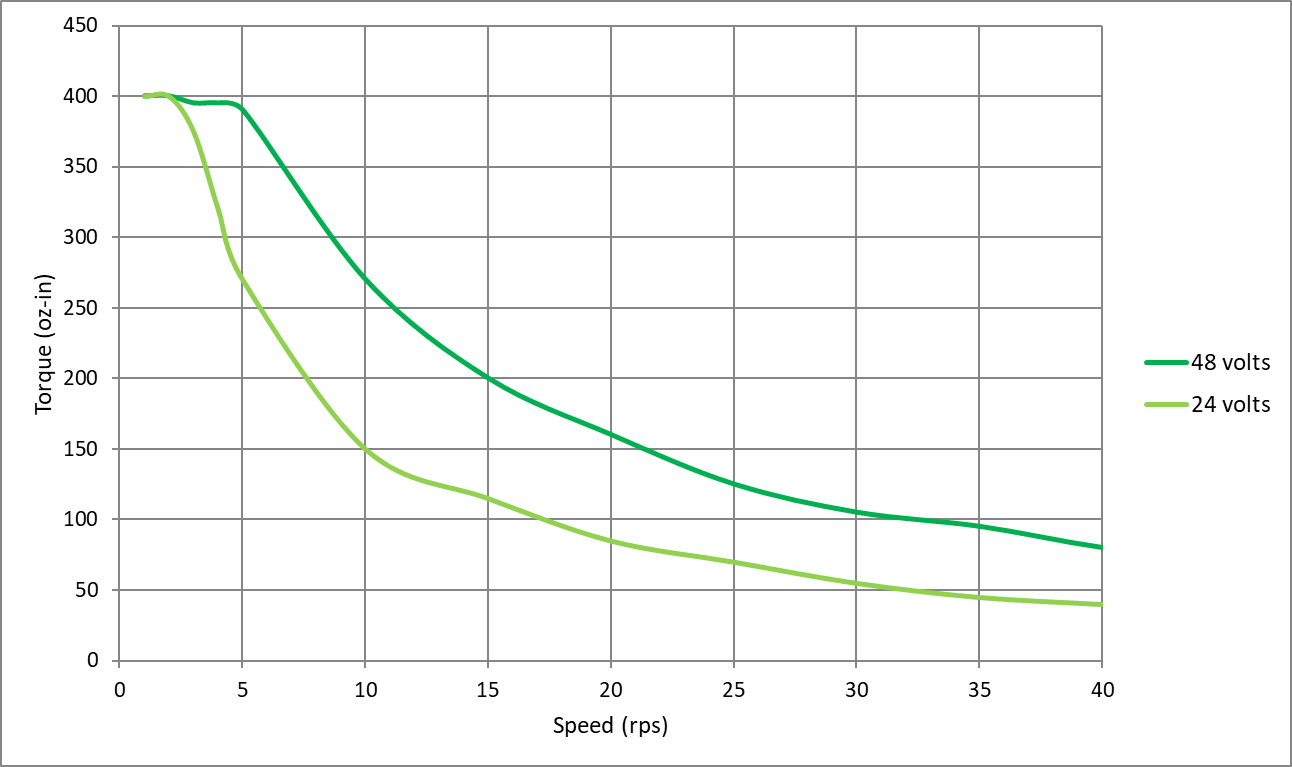
Figure 2 — two speed-torque curves of the same step motor and drive combination. Only the power supply voltage is different. The dark green line shows stall torque with a 48-V power supply. The light green line shows stall torque with a 24-V supply. A 12-V supply would spur an even lower curve.

4. ‘Can’t I run this step motor with a couple of PLC outputs? Why do a need a drive?’

Two-phase stepper drives use a set of eight transistors connected to form an H-bridge. Creating an equivalent H-bridge from PLC outputs would require eight outputs. Some two-phase step motors with six lead wires are driven with as few as four transistors. For these, you could use four PLC outputs to rotate a step motor forward and backward. However, a stepper drive does much more than simply sequence the transistors in the H-bridge.

Stepper drives regulate the current in each phase of the motor using PWM switching of the bus voltage. As noted in the previous section on voltage, the supply voltage must be high enough to overcome BEMF and produce torque at speed.

Stepper drives with microstepping capabilities further refine the PWM switching logic to ratio the current in each phase according to a sine wave, getting finer positioning than a step motor’s basic step angle. Moving beyond the most basic stepper drives, those that have trajectory generators on board can automatically ramp the motor speed up and down according to preset acceleration and deceleration rates.

Using PLC outputs to drive a step motor could be a neat project for someone interested in dissecting how step motors work. For any serious motion-control project, you’ll want a proper drive.

5. ‘The motor is so noisy … there must be something wrong with it.’

Every time a step motor takes a step, it generates a little bit of ringing noise as the rotor settles into position (think of the classic mass on a spring). The ringing is the motor’s natural resonant frequency, which is based on the motor construction. The natural resonant frequency is amplified when the frequency of motor steps approaches or equals it.

This noise is most pronounced when the step motor is driven in full step sequence (the lowest resolution available; equal to the motor’s step angle) and at low speeds, typically in the range of 1 to 5 revolutions per second.

The question of noise most often arises when a user tests a step motor for the first time with the motor unmounted and uncoupled to any load. In this scenario, the motor is free to resonate as much as it likes without anything to damp the resonance.

Fortunately, a few easy steps can mitigate the resonance:

  • Add mechanical damping to the system by mounting the motor and coupling the motor shaft to a load. Coupling the shaft to a load adds some amount of inertia or friction to the system … and that in turn alters or damps the motor’s natural resonant frequency.
  • Reduce the step angle with microstepping. When microstepping, the step angle is much smaller with each step and the natural resonant frequency is excited less.

If neither of these steps works, consider using a stepper drive with an anti-resonance algorithm built into its current control logic.

6. ‘I need an encoder to run a step motor, right?’

No, an encoder is not required to run a step motor in open-loop control. Step motors are the only type of brushless DC motor that accurately and repeatedly position a load using open-loop control. Other motors need some type of position feedback. Open-loop control works well when:

  • Motion tasks are the same over time.
  • The load doesn’t change.
  • The required speeds are relatively low.
  • Failure to complete the motion task does not result in critical or dangerous machine failure.

If the application doesn’t meet the stated criteria, consider introducing feedback into the system to permit some level of closed-loop control. Adding an encoder to a step motor system offers benefits ranging from basic functions that are essentially open-loop control but with subtle, effective improvements, to fully closed-loop control where the step motor operates as part of a servo control system. Contact your step motor and drive supplier for information on the range of feedback and closed-loop control options they offer.

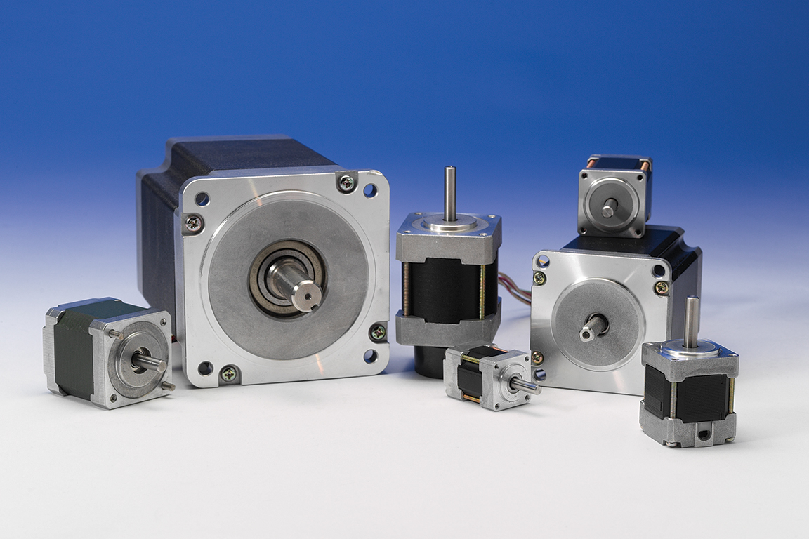
Applied Motion Products step motors come in a wide range of frame sizes — from NEMA 8 to NEMA 42 and beyond.

Editor’s note: This article originally ran on Design World, a sibling site of The Robot Report.

The post 6 common step motor mistakes to avoid in automation applications appeared first on The Robot Report.

TIAGo++ robot from PAL Robotics ready for two-armed tasks

Among the challenges for developers of mobile manipulation and humanoid robots is the need for an affordable and flexible research platform. PAL Robotics last month announced its TIAGo++, a robot that includes two arms with seven degrees of freedom each.

As with PAL Robotics‘ one-armed TIAGo, the new model is based on the Robot Operating System (ROS) and can be expanded with additional sensors and end effectors. TIAGo++ is intended to enable engineers to create applications that include a touchscreen interface for human-robot interaction (HRI) and require simultaneous perception, bilateral manipulation, mobility, and artificial intelligence.

In addition, TIAGo++ supports NVIDIA’s Jetson TX2 as an extra for machine learning and deep learning development. Tutorials for ROS and open-source simulation for TIAGo are available online.

Barcelona, Spain-based PAL, which was named a “Top 10 ROS-based robotics company to watch in 2019,” also makes the Reem and TALOS robots.

Jordi Pagès, product manager of the TIAGo robot at PAL Robotics responded to the following questions about TIAGo++ from The Robot Report:

For the development of TIAGo++, how did you collect feedback from the robotics community?

Pagès: PAL Robotics has a long history in research and development. We have been creating service robotics platforms since 2004. When we started thinking about the TIAGo robot development, we asked researchers from academia and industry which features would they expect or value in a platform for research.

Our goal with TIAGo has always been the same: to deliver a robust platform for research that easily adapts to diverse robotics projects and use cases. That’s why it was key to be in touch with the robotics and AI developers from start.

After delivering the robots, we usually ask for feedback and stay in touch with the research centers to learn about their activities and experiences, and the possible improvements or suggestions they would have. We do the same with the teams that use TIAGo for competitions like RoboCup or the European Robotics League [ERL].

At the same time, TIAGo is used in diverse European-funded projects where end users from different sectors, from healthcare to industry, are involved. This allows us to also learn from their feedback and keep finding new ways in which the platform could be of help in a user-centered way. That’s how we knew that adding a second arm into the TIAGo portfolio of its modular possibilities could be of help to the robotics community.

How long did it take PAL Robotics to develop the two-armed TIAGo++ in comparison with the original model?

Pagès: Our TIAGo platform is very modular and robust, so it took us just few months from taking the decision to having a working TIAGo++ ready to go. The modularity of all our robots and our wide experience developing humanoids usually helps us a lot in reducing the redesign and production time.

The software is also very modular, with extensive use of ROS, the de facto standard robotics middleware. Our customers are able to upgrade, modify, and substitute ROS packages. That way, they can focus their attention on their real research on perception, navigation, manipulation, HRI, and AI.

How high can TIAGo++ go, and what’s its reach?

Pagès: TIAGo++ can reach the floor and up to 1.75m [5.74 ft.] high with each arm, thanks to the combination of its 7 DoF [seven degrees of freedom] arms and its lifting torso. The maximum extension of each arm is 92cm [36.2 in.]. In our experience, this workspace allows TIAGo to work in several environments like domestic, healthcare, and industry.

TIAGo++ robot from PAL Robotics

The TIAGo can extend in height, and each arm has a reach of about 3 ft. Source: PAL Robotics

What’s the advantage of seven degrees of freedom for TIAGo’s arms over six degrees?

Pagès: A 7-DoF arm is much better in this sense for people who will be doing manipulation tasks. Adding more DoFs means that the robot can arrive to more poses — positions and orientations — of its arm and end-effector that it couldn’t reach before.

Also, this enables developers to reduce singularities, avoiding non-desired abrupt movements. This means that TIAGo has more possibilities to move its arm and reach a certain pose in space, with a more optimal combination of movements.

What sensors and motors are in the robot? Are they off-the-shelf or custom?

Pagès: All our mobile-based platforms, like the TIAGo robot, combine many sensors. TIAGo has a laser and sonars to move around and localize itself in space, an IMU [inertial measurement unit], and an RGB-D camera in the head. It can have a force/torque sensor on the wrist, especially useful to work in HRI scenarios. It also has a microphone and a speaker.

TIAGo has current sensing in every joint of the arm, enabling a very soft, effortless torque control on each of the arms. The possibility of having an expansion panel with diverse connectors makes it really easy for developers to add even more sensors to it, like a thermal camera or a gripper camera, once they have TIAGo in their labs.

About the motors, TIAGo++ makes use our custom joints integrating high-quality commercial components and our own electronic power management and control. All motors also have encoders to measure the current motor position.

What’s the biggest challenge that a humanoid like TIAGo++ can help with?

Pagès: TIAGo++ can help with are those tasks that require bi-manipulation, in combination with navigation, perception, HRI, or AI. Even though it is true that a one-arm robot can already perform a wide range of tasks, there are many actions in our daily life that require of two arms, or that are more comfortably or quickly done with two arms rather than one.

For example, two arms are good for grasping and carrying a box, carrying a platter, serving liquids, opening a bottle or a jar, folding clothes, or opening a wardrobe while holding an object. In the end, our world and tools have been designed for the average human body, which is with two arms, so TIAGo++ can adapt to that.

As a research platform based on ROS, is there anything that isn’t open-source? Are navigation and manipulation built in or modular?

Pagès: Most software is provided either open-sourced or with headers and dynamic libraries so that customers can develop applications making use of the given APIs or using the corresponding ROS interfaces at runtime.

For example, all the controllers in TIAGo++ are plugins of ros_control, so customers can implement their own controllers following our public tutorials and deploy them on the real robot or in the simulation.

Moreover, users can replace any ROS package by their own packages. This approach is very modular, and even if we provide navigation and manipulation built-in, developers can use their own navigation and manipulation instead of ours.

Did PAL work with NVIDIA on design and interoperability, or is that an example of the flexibility of ROS?

Pagès: It is both an example of how easy is to expand TIAGo with external devices and how easy is to integrate in ROS these devices.

One example of applications that our clients have developed using the NVIDIA Jetson TX2 is the “Bring me a beer” task from the Homer Team [at RoboCup], at the University of Koblenz-Landau. They made a complete application in which TIAGo robot could understand a natural language request, navigate autonomously to the kitchen, open the fridge, recognize and select the requested beer, grasp it, and deliver it back to the person who asked for it.

As a company, we work with multiple partners, but we also believe that our users should be able to have a flexible platform that allows them to easily integrate off-the-shelf solutions they already have.

How much software support is there for human-machine interaction via a touchscreen?

Pagès: The idea behind integrating a touchscreen on TIAGo++ is to bring customers the possibility to implement their own graphical interface, so we provide full access to the device. We work intensively with researchers, and we provide platforms as open as our customers need, such as a haptic interface.

What do robotics developers need to know about safety and security?

Pagès: A list of safety measures and best practices are provided in the Handbook of TIAGo robot in order that customers ensure safety both around the robot and for the robot itself.

TIAGo also features some implicit control modes that help to ensure safety while operation. For example, an effort control mode for the arms is provided so that collisions can be detected and the arm can be set in gravity compensation mode.

Furthermore, the wrist can include a six-axis force/torque sensor providing more accurate feedback about collisions or interactions of the end effector with the environment. This sensor can be also used to increase the safety of the robot. We provide this information to our customers and developers so they are always aware about the safety measures.

Have any TIAGo users moved toward commercialization based on what they’ve learned with PAL’s systems?

Pagès: At the moment, from the TIAGo family, we commercialize the TIAGo Base for intralogistics automation in indoor spaces such as factories or warehouses.

Some configurations of the TIAGo robot have been tested in pilots in healthcare applications. In the EnrichMe H2020 EU Project, the robot gave assistance to old people at home autonomously for up to approximately two months.

In robotics competitions such as the ERL, teams have shown the quite outstanding performance of TIAGo in accomplishing specific actions in a domestic environment. Two teams ended first and third in the RoboCup@Home OPL 2019 in Sydney, Australia. The Homer Team won for the third time in a row using TIAGo — see it clean a toilet here.

The CATIE Robotics Team ended up third in the first world championship in which it participated. For instance, in one task, it took out the trash.

The TIAGo robot is also used for European Union Horizon 2020 experiments in which collaborative robots that combine mobility with manipulation are used in industrial scenarios. This includes projects such as MEMMO for motion generation, Co4Robots for coordination, and RobMoSys for open-source software development.

Besides this research aspect, we have industrial customers that are using TIAGo to improve their manufacturing procedures.

How does TIAGo++ compare with, say, Rethink Robotics’ Baxter?

Pagès: With TIAGo++, besides the platform itself, you also get support, extra advanced software solutions, and assessment from a company that continues to be in the robotics sector since more than 15 years ago. Robots like the TIAGo++ also use our know-how both in software and hardware, a knowledge that the team has been gathering from the development of cutting-edge biped humanoids like the torque-controlled TALOS.

From a technical point of view, TIAGo++ was made very compact to suit environments shared with people such as homes. Baxter was a very nice entry-point platform and was not originally designed to be a mobile manipulator but a fixed one. TIAGo++ can use the same navigation used in our commercial autonomous mobile robot for intralogistics tasks, the TIAGo Base.

Besides, TIAGo++ is a fully customizable robot in all aspects: You can select the options you want in hardware and software, so you get the ideal platform you want to have in your robotics lab. For a mobile manipulator with two 7-DoF arms, force/torque sensors, ROS-based, affordable, and with community support, we believe TIAGo++ should be a very good option.

The TIAGo community is growing around the world, and we are sure that we will see more and more robots helping people in different scenarios very soon.

What’s the price point for TIAGo++?

Pagès: The starting price is around €90,000 [$100,370 U.S.]. It really depends on the configuration, devices, computer power, sensors, and extras that each client can choose for their TIAGo robot, so the price can vary.

The post TIAGo++ robot from PAL Robotics ready for two-armed tasks appeared first on The Robot Report.

Microrobots activated by laser pulses could deliver medicine to tumors

Targeting medical treatment to an ailing body part is a practice as old as medicine itself. Drops go into itchy eyes. A broken arm goes into a cast. But often what ails us is inside the body and is not so easy to reach. In such cases, a treatment like surgery or chemotherapy might be called for. A pair of researchers in Caltech’s Division of Engineering and Applied Science are working on an entirely new form of treatment — microrobots that can deliver drugs to specific spots inside the body while being monitored and controlled from outside the body.

“The microrobot concept is really cool because you can get micromachinery right to where you need it,” said Lihong Wang, Bren Professor of Medical Engineering and Electrical Engineering at the California Institute of Technology. “It could be drug delivery, or a predesigned microsurgery.”

The microrobots are a joint research project of Wang and Wei Gao, assistant professor of medical engineering, and are intended for treating tumors in the digestive tract.

Developing jet-powered microrobots

The microrobots consist of microscopic spheres of magnesium metal coated with thin layers of gold and parylene, a polymer that resists digestion. The layers leave a circular portion of the sphere uncovered, kind of like a porthole. The uncovered portion of the magnesium reacts with the fluids in the digestive tract, generating small bubbles. The stream of bubbles acts like a jet and propels the sphere forward until it collides with nearby tissue.

On their own, magnesium spherical microrobots that can zoom around might be interesting, but they are not especially useful. To turn them from a novelty into a vehicle for delivering medication, Wang and Gao made some modifications to them.

First, a layer of medication is sandwiched between an individual microsphere and its parylene coat. Then, to protect the microrobots from the harsh environment of the stomach, they are enveloped in microcapsules made of paraffin wax.

Laser-guided delivery

At this stage, the spheres are capable of carrying drugs, but still lack the crucial ability to deliver them to a desired location. For that, Wang and Gao use photoacoustic computed tomography (PACT), a technique developed by Wang that uses pulses of infrared laser light.

The infrared laser light diffuses through tissues and is absorbed by oxygen-carrying hemoglobin molecules in red blood cells, causing the molecules to vibrate ultrasonically. Those ultrasonic vibrations are picked up by sensors pressed against the skin. The data from those sensors is used to create images of the internal structures of the body.

Previously, Wang has shown that variations of PACT can be used to identify breast tumors, or even individual cancer cells. With respect to the microrobots, the technique has two jobs. The first is imaging. By using PACT, the researchers can find tumors in the digestive tract and also track the location of the microrobots, which show up strongly in the PACT images.

Microrobots activated by laser pulses could deliver medicine to tumors

Microrobots activated by lasers and powered by magnesium jets could deliver medicine within the human body. Source: Caltech

Once the microrobots arrive in the vicinity of the tumor, a high-power continuous-wave near-infrared laser beam is used to activate them. Because the microrobots absorb the infrared light so strongly, they briefly heat up, melting the wax capsule surrounding them, and exposing them to digestive fluids.

At that point, the microrobots’ bubble jets activate, and the microrobots begin swarming. The jets are not steerable, so the technique is sort of a shotgun approach — the microrobots will not all hit the targeted area, but many will. When they do, they stick to the surface and begin releasing their medication payload.

“These micromotors can penetrate the mucus of the digestive tract and stay there for a long time. This improves medicine delivery,” Gao says. “But because they’re made of magnesium, they’re biocompatible and biodegradable.”

Pushing the concept

Tests in animal models show that the microrobots perform as intended, but Gao and Wang say they are planning to continue pushing the research forward.

“We demonstrated the concept that you can reach the diseased area and activate the microrobots,” Gao says. “The next step is evaluating the therapeutic effect of them.”

Gao also says he would like to develop variations of the microrobots that can operate in other parts of the body, and with different types of propulsion systems.

Wang says his goal is to improve how his PACT system interacts with the microrobots. The infrared laser light it uses has some difficulty reaching into deeper parts of the body, but he says it should be possible to develop a system that can penetrate further.

The paper describing the microrobot research, titled, “A microrobotic system guided by photoacoustic tomography for targeted navigation in intestines in vivo,” appears in the July 24 issue of Science Robotics. Other co-authors include Zhiguang Wu, Lei Li, Yiran Yang (MS ’18), Yang Li, and So-Yoon Yang of Caltech; and Peng Hu of Washington University in St. Louis. Funding for the research was provided by the National Institutes of Health and Caltech’s Donna and Benjamin M. Rosen Bioengineering Center.

Editor’s note: This article republished from the California Institute of Technology.

The post Microrobots activated by laser pulses could deliver medicine to tumors appeared first on The Robot Report.

Automated system from MIT generates robotic actuators for novel tasks

An automated system developed by MIT researchers designs and 3D prints complex robotic parts called actuators that are optimized according to an enormous number of specifications.

An automated system developed by MIT researchers designs and 3D prints complex robotic parts called actuators that are optimized according to an enormous number of specifications. Credit: Subramanian Sundaram

CAMBRIDGE, Mass. — An automated system developed by researchers at the Massachusetts Institute of Technology designs and 3D prints complex robotic actuators that are optimized according to an enormous number of specifications. In short, the system does automatically what is virtually impossible for humans to do by hand.

In a paper published in Science Advances, the researchers demonstrated the system by fabricating actuators that show different black-and-white images at different angles. One actuator, for instance, portrays a Vincent van Gogh portrait when laid flat. When it’s activated, it tilts at an angle and displays the famous Edvard Munch painting “The Scream.”

The actuators are made from a patchwork of three different materials, each with a different light or dark color and a property — such as flexibility and magnetization — that controls the actuator’s angle in response to a control signal. Software first breaks down the actuator design into millions of three-dimensional pixels, or “voxels,” that can each be filled with any of the materials.

Then, it runs millions of simulations, filling different voxels with different materials. Eventually, it lands on the optimal placement of each material in each voxel to generate two different images at two different angles. A custom 3D printer then fabricates the actuator by dropping the right material into the right voxel, layer by layer.

“Our ultimate goal is to automatically find an optimal design for any problem, and then use the output of our optimized design to fabricate it,” said first author Subramanian Sundaram, Ph.D. ’18, a former graduate student in MIT’s Computer Science and Artificial Intelligence Laboratory (CSAIL). “We go from selecting the printing materials, to finding the optimal design, to fabricating the final product in almost a completely automated way.”

New robotic actuators mimic biology for efficiency

The shifting images demonstrates what the system can do. But actuators optimized for appearance and function could also be used for biomimicry in robotics. For instance, other researchers are designing underwater robotic skins with actuator arrays meant to mimic denticles on shark skin. Denticles collectively deform to decrease drag for faster, quieter swimming.

“You can imagine underwater robots having whole arrays of actuators coating the surface of their skins, which can be optimized for drag and turning efficiently, and so on,” Sundaram said.

Joining Sundaram on the paper were Melina Skouras, a former MIT postdoc; David S. Kim, a former researcher in the Computational Fabrication Group; Louise van den Heuvel ’14, SM ’16; and Wojciech Matusik, an MIT associate professor in electrical engineering and computer science and head of the Computational Fabrication Group.

Navigating the ‘combinatorial explosion’

Robotic actuators are becoming increasingly complex. Depending on the application, they must be optimized for weight, efficiency, appearance, flexibility, power consumption, and various other functions and performance metrics. Generally, experts manually calculate all those parameters to find an optimal design.

Adding to that complexity, new 3D-printing techniques can now use multiple materials to create one product. That means the design’s dimensionality becomes incredibly high

“What you’re left with is what’s called a ‘combinatorial explosion,’ where you essentially have so many combinations of materials and properties that you don’t have a chance to evaluate every combination to create an optimal structure,” Sundaram said.

The researchers first customized three polymer materials with specific properties they needed to build their robotic actuators: color, magnetization, and rigidity. They ultimately produced a near-transparent rigid material, an opaque flexible material used as a hinge, and a brown nanoparticle material that responds to a magnetic signal. They plugged all that characterization data into a property library.

The system takes as input grayscale image examples — such as the flat actuator that displays the Van Gogh portrait but tilts at an exact angle to show “The Scream.” It basically executes a complex form of trial and error that’s somewhat like rearranging a Rubik’s Cube, but in this case around 5.5 million voxels are iteratively reconfigured to match an image and meet a measured angle.

Initially, the system draws from the property library to randomly assign different materials to different voxels. Then, it runs a simulation to see if that arrangement portrays the two target images, straight on and at an angle. If not, it gets an error signal. That signal lets it know which voxels are on the mark and which should be changed.

Adding, removing, and shifting around brown magnetic voxels, for instance, will change the actuator’s angle when a magnetic field is applied. But, the system also has to consider how aligning those brown voxels will affect the image.

MIT robotic actuator

Credit: Subramanian Sundaram

Voxel by voxel

To compute the actuator’s appearances at each iteration, the researchers adopted a computer graphics technique called “ray-tracing,” which simulates the path of light interacting with objects. Simulated light beams shoot through the actuator at each column of voxels.

Actuators can be fabricated with more than 100 voxel layers. Columns can contain more than 100 voxels, with different sequences of the materials that radiate a different shade of gray when flat or at an angle.

When the actuator is flat, for instance, the light beam may shine down on a column containing many brown voxels, producing a dark tone. But when the actuator tilts, the beam will shine on misaligned voxels. Brown voxels may shift away from the beam, while more clear voxels may shift into the beam, producing a lighter tone.

The system uses that technique to align dark and light voxel columns where they need to be in the flat and angled image. After 100 million or more iterations, and anywhere from a few to dozens of hours, the system will find an arrangement that fits the target images.

“We’re comparing what that [voxel column] looks like when it’s flat or when it’s titled, to match the target images,” Sundaram said. “If not, you can swap, say, a clear voxel with a brown one. If that’s an improvement, we keep this new suggestion and make other changes over and over again.”

To fabricate the actuators, the researchers built a custom 3-D printer that uses a technique called “drop-on-demand.” Tubs of the three materials are connected to print heads with hundreds of nozzles that can be individually controlled. The printer fires a 30-micron-sized droplet of the designated material into its respective voxel location. Once the droplet lands on the substrate, it’s solidified. In that way, the printer builds an object, layer by layer.

The work could be used as a stepping stone for designing larger structures, such as airplane wings, Sundaram says. Researchers, for instance, have similarly started breaking down airplane wings into smaller voxel-like blocks to optimize their designs for weight and lift, and other metrics.

“We’re not yet able to print wings or anything on that scale, or with those materials,” said Sundaram. “But I think this is a first step toward that goal.”

Editor’s note: This article republished with permission from MIT News.

The post Automated system from MIT generates robotic actuators for novel tasks appeared first on The Robot Report.

R-Series actuator from Hebi Robotics is ready for outdoor rigors

PITTSBURGH — What do both summer vacationers and field robots need to do? Get into the water. Hebi Robotics this week announced the availability of its R-Series actuators, which it said can enable engineers “to quickly create custom robots that can be deployed directly in wet, dirty, or outdoor environments.”

Hebi Robotics was founded in 2014 by Carnegie Mellon University professor and robotics pioneer Howie Choset. It makes hardware and software for developers to build robots for their specific applications. It also offers custom development services to make robots “simple, useful, and safe.”

Hebi’s team includes experts in robotics, particularly in motion control. The company has developed robotics tools for academic, aerospace military, sewer inspection, and spaceflight users.

Robots can get wet and dirty with R-Series actuators

The R-Series actuator is built on Hebi’s X-Series platform. It is sealed to IP678 and is designed to be lightweight, compact, and energy-efficient. The series includes three models, the R8-3, which has continuous torque of 3 N-m and weighs 670g; the RB-9, which has continuous torque of 8 N-m and weighs 685g; and the R8-16, which has continuous torque of 16 N-m and weighs 715g.

Hebi's R-Series actuator

The R-Series actuator is sealed for wet and dirty environments. Source: Hebi Robotics

The actuators also include sensors that Hebi said “enable simultaneous control of position, velocity, and torque, as well as three-axis inertial measurement.”

In addition, the R-Series integrates a brushless motor, gear reduction, force sensing, encoders, and controls in a compact package, said Hebi. The actuators can run on 24-48V DC, include internal pressure sensors, and communicate via 100Mbps Ethernet.

On the software side, the R-Series has application programming interfaces (APIs) for MATLAB, the Robot Operating System (ROS), Python, C and C++, and C#, as well as support for Windows, Linux, and OS X.

According to Hebi Robotics, the R-Series actuators will be available this autumn, and it is accepting pre-orders at 10% off the list prices. The actuator costs $4,500, and kits range from $20,000 to $36,170, depending on the number of degrees of freedom of the robotic arm. Customers should inquire about pricing for the hexapod kit.

The post R-Series actuator from Hebi Robotics is ready for outdoor rigors appeared first on The Robot Report.

Self-driving cars may not be best for older drivers, says Newcastle University study

Self-driving cars may not be best for older drivers, says Newcastle University study

VOICE member Ian Fairclough and study lead Dr. Shuo Li in test of older drivers. Source: Newcastle University

With more people living longer, driving is becoming increasingly important in later life, helping older drivers to stay independent, socially connected and mobile.

But driving is also one of the biggest challenges facing older people. Age-related problems with eyesight, motor skills, reflexes, and cognitive ability increase the risk of an accident or collision and the increased frailty of older drivers mean they are more likely to be seriously injured or killed as a result.

“In the U.K., older drivers are tending to drive more often and over longer distances, but as the task of driving becomes more demanding we see them adjust their driving to avoid difficult situations,” explained Dr Shuo Li, an expert in intelligent transport systems at Newcastle University.

“Not driving in bad weather when visibility is poor, avoiding unfamiliar cities or routes and even planning journeys that avoid right-hand turns are some of the strategies we’ve seen older drivers take to minimize risk. But this can be quite limiting for people.”

Potential game-changer

Self-driving cars are seen as a potential game-changer for this age group, Li noted. Fully automated, they are unlikely to require a license and could negotiate bad weather and unfamiliar cities under all situations without input from the driver.

But it’s not as clear-cut as it seems, said Li.

“There are several levels of automation, ranging from zero where the driver has complete control, through to Level 5, where the car is in charge,” he explained. “We’re some way-off Level 5, but Level 3 may be a trend just around the corner.  This will allow the driver to be completely disengaged — they can sit back and watch a film, eat, even talk on the phone.”

“But, unlike level four or five, there are still some situations where the car would ask the driver to take back control and at that point, they need to be switched on and back in driving mode within a few seconds,” he added. “For younger people that switch between tasks is quite easy, but as we age, it becomes increasingly more difficult and this is further complicated if the conditions on the road are poor.”

Newcastle University DriveLAB tests older drivers

Led by Newcastle University’s Professor Phil Blythe and Dr Li, the Newcastle University team have been researching the time it takes for older drivers to take back control of an automated car in different scenarios and also the quality of their driving in these different situations.

Using the University’s state-of-the-art DriveLAB simulator, 76 volunteers were divided into two different age groups (20-35 and 60-81).

They experienced automated driving for a short period and were then asked to “take back” control of a highly automated car and avoid a stationary vehicle on a motorway, a city road, and in bad weather conditions when visibility was poor.

The starting point in all situations was “total disengagement” — turned away from the steering wheel, feet out of the foot well, reading aloud from an iPad.

The time taken to regain control of the vehicle was measured at three points; when the driver was back in the correct position (reaction time), “active input” such as braking and taking the steering wheel (take-over time), and finally the point at which they registered the obstruction and indicated to move out and avoid it (indicator time).

“In clear conditions, the quality of driving was good but the reaction time of our older volunteers was significantly slower than the younger drivers,” said Li. “Even taking into account the fact that the older volunteers in this study were a really active group, it took about 8.3 seconds for them to negotiate the obstacle compared to around 7 seconds for the younger age group. At 60mph, that means our older drivers would have needed an extra 35m warning distance — that’s equivalent to the length of 10 cars.

“But we also found older drivers tended to exhibit worse takeover quality in terms of operating the steering wheel, the accelerator and the brake, increasing the risk of an accident,” he said.

In bad weather, the team saw the younger drivers slow down more, bringing their reaction times more in line with the older drivers, while driving quality dropped across both age groups.

In the city scenario, this resulted in 20 collisions and critical encounters among the older participants compared to 12 among the younger drivers.

Newcastle University DriveLab

VOICE member Pat Wilkinson. Source: Newcastle University

Designing automated cars of the future

The research team also explored older drivers’ opinions and requirements towards the design of automated vehicles after gaining first-hand experience with the technologies on the driving simulator.

Older drivers were generally positive towards automated vehicles but said they would want to retain some level of control over their automated cars. They also felt they required regular updates from the car, similar to a SatNav, so the driver has an awareness of what’s happening on the road and where they are even when they are busy with another activity.

The research team are now looking at how the vehicles can be improved to overcome some of these problems and better support older drivers when the automated cars hit our roads.

“I believe it is critical that we understand how new technology can support the mobility of older people and, more importantly, that new transport systems are designed to be age friendly and accessible,” said Newcastle University Prof. Phil Blythe, who led the study and is chief scientific advisor for the U.K. Department for Transport. “The research here on older people and the use of automated vehicles is only one of many questions we need to address regarding older people and mobility.”

“Two pillars of the Government’s Industrial strategy are the Future of Mobility Grand Challenge and the Ageing Society Grand Challenge,” he added. “Newcastle University is at the forefront of ensuring that these challenges are fused together to ensure we shape future mobility systems for the older traveller, who will be expecting to travel well into their eighties and nineties.”

“It is critical that we understand how new technology can support the mobility of older people and, more importantly, that new transport systems are designed to be age friendly and accessible,” — Newcastle University Prof. Phil Blythe

Case studies of older drivers

Pat Wilkinson, who lives in Rowland’s Gill, County Durham, has been supporting the DriveLAB research for almost nine years.

Now 74, the former Magistrate said it’s interesting to see how technology is changing and gradually taking the control – and responsibility – away from the driver.

“I’m not really a fan of the cars you don’t have to drive,” she said. “As we get older, our reactions slow, but I think for the young ones, chatting on their phones or looking at the iPad, you just couldn’t react quickly if you needed to either. I think it’s an accident waiting to happen, whatever age you are.”

“And I enjoy driving – I think I’d miss that,” Wilkinson said. “I’ve driven since I first passed my test in my 20s, and I hope I can keep on doing so for a long time.

“I don’t think fully driverless cars will become the norm, but I do think the technology will take over more,” she said. “I think studies like this that help to make it as safe as possible are really important.”

Ian Fairclough, 77 from Gateshead, added: “When you’re older and the body starts to give up on you, a car means you can still have adventures and keep yourself active.”

“I passed my test at 22 and was in the army for 25 years, driving all sorts of vehicles in all terrains and climates,” he recalled. “Now I avoid bad weather, early mornings when the roads are busy and late at night when it’s dark, so it was really interesting to take part in this study and see how the technology is developing and what cars might be like a few years from now.”

Fairclough took part in two of the studies in the VR simulator and said it was difficult to switch your attention quickly from one task to another.

“It feels very strange to be a passenger one minute and the driver the next,” he said. “But I do like my Toyota Yaris. It’s simple, clear and practical.  I think perhaps you can have too many buttons.”

Wilkinson and Fairclough became involved in the project through VOICE, a group of volunteers working together with researchers and businesses to identify the needs of older people and develop solutions for a healthier, longer life.

The post Self-driving cars may not be best for older drivers, says Newcastle University study appeared first on The Robot Report.

KIST researchers teach robot to trap a ball without coding

KIST teaching

KIST’s research shows that robots can be intuitively taught to be flexible by humans rather than through numerical calculation or programming the robot’s movements. Credit: KIST

The Center for Intelligent & Interactive Robotics at the Korea Institute of Science and Technology, or KIST, said that a team led by Dr. Kee-hoon Kim has developed a way of teaching “impedance-controlled robots” through human demonstrations. It uses surface electromyograms of muscles and succeeded in teaching a robot to trap a dropped ball like a soccer player.

A surface electromyogram (sEMG) is an electric signal produced during muscle activation that can be picked up on the surface of the skin, said KIST, which is led by Pres. Byung-gwon Lee.

Recently developed impedance-controlled robots have opened up a new era of robotics based on the natural elasticity of human muscles and joints, which conventional rigid robots lack. Robots with flexible joints are expected to be able to run, jump hurdles and play sports like humans. However, the technology required to teach such robots to move in this manner has been unavailable until recently.

KIST uses human muscle signals to teach robots how to move

The KIST research team claimed to be the first in the world to develop a way of teaching new movements to impedance-controlled robots using human muscle signals. With this technology, which detects not only human movements but also muscle contractions through sEMG, it’s possible for robots to imitate movements based on human demonstrations.

Dr. Kee-hoon Kim’s team said it succeeded in using sEMG to teach a robot to quickly and adroitly trap a rapidly falling ball before it comes into contact with a solid surface or bounces too far to reach — similar to the skills employed by soccer players.

SEMG sensors were attached to a man’s arm, allowing him to simultaneously control the location and flexibility of the robot’s rapid upward and downward movements. The man then “taught” the robot how to trap a rapidly falling ball by giving a personal demonstration. After learning the movement, the robot was able to skillfully trap a dropped ball without any external assistance.

KIST movements

sEMG sensors attached to a man’s arm, allowed him to control the location and flexibility of a robot’s rapid movements. Source: KIST

This research outcome, which shows that robots can be intuitively taught to be flexible by humans, has attracted much attention, as it was not accomplished through numerical calculation or programming of the robot’s movements. This study is expected to help advance the study of interactions between humans and robots, bringing us one step closer to a world in which robots are an integral part of our daily lives.

Kim said, “The outcome of this research, which focuses on teaching human skills to robots, is an important achievement in the study of interactions between humans and robots.”

TRI tackles manipulation research for reliable, robust human-assist robots

Wouldn’t it be amazing to have a robot in your home that could work with you to put away the groceries, fold the laundry, cook your dinner, do the dishes, and tidy up before the guests come over? For some of us, a robot assistant – a teammate – might only be a convenience.

But for others, including our growing population of older people, applications like this could be the difference between living at home or in an assisted care facility. Done right, we believe these robots will amplify and augment human capabilities, allowing us to enjoy longer, healthier lives.

Decades of prognostications about the future – largely driven by science fiction novels and popular entertainment – have encouraged public expectations that someday home robots will happen. Companies have been trying for years to deliver on such forecasts and figure out how to safely introduce ever more capable robots into the unstructured home environment.

Despite this age of tremendous technological progress, the robots we see in homes to date are primarily vacuum cleaners and toys. Most people don’t realize how far today’s best robots are from being able to do basic household tasks. When they see heavy use of robot arms in factories or impressive videos on YouTube showing what a robot can do, they might reasonably expect these robots could be used in the home now.

Bringing robots into the home

Why haven’t home robots materialized as quickly as some have come to expect? One big challenge is reliability. Consider:

  • If you had a robot that could load dishes into the dishwasher for you, what if it broke a dish once a week?
  • Or, what if your child brings home a “No. 1 DAD!” mug that she painted at the local art studio, and after dinner, the robot discards that mug into the trash because it didn’t recognize it as an actual mug?

A major barrier for bringing robots into the home are core unsolved problems in manipulation that prevent reliability. As I presented this week at the Robotics: Science and Systems conference, the Toyota Research Institute (TRI) is working on fundamental issues in robot manipulation to tackle these unsolved reliability challenges. We have been pursuing a unique combination of robotics capabilities focused on dexterous tasks in an unstructured environment.

Unlike the sterile, controlled and programmable environment of the factory, the home is a “wild west” – unstructured and diverse. We cannot expect lab tests to account for every different object that a robot will see in your home. This challenge is sometimes referred to as “open-world manipulation,” as a callout to “open-world” computer games.

Despite recent strides in artificial intelligence and machine learning, it is still very hard to engineer a system that can deal with the complexity of a home environment and guarantee that it will (almost) always work correctly.

TRI addresses the reliability gap

Above is a demonstration video showing how TRI is exploring the challenge of robustness that addresses the reliability gap. We are using a robot loading dishes in a dishwasher as an example task. Our goal is not to design a robot that loads the dishwasher, but rather we use this task as a means to develop the tools and algorithms that can in turn be applied in many different applications.

Our focus is not on hardware, which is why we are using a factory robot arm in this demonstration rather than designing one that would be more appropriate for the home kitchen.

The robot in our demonstration uses stereo cameras mounted around the sink and deep learning algorithms to perceive objects in the sink. There are many robots out there today that can pick up almost any object — random object clutter clearing has become a standard benchmark robotics challenge. In clutter clearing, the robot doesn’t require much understanding about an object — perceiving the basic geometry is enough.

For example, the algorithm doesn’t need to recognize if the object is a plush toy, a toothbrush, or a coffee mug. Given this, these systems are also relatively limited with what they can do with those objects; for the most part, they can only pick up the objects and drop them in another location only. In the robotics world, we sometimes refer to these robots as “pick and drop.”

Loading the dishwasher is actually significantly harder than what most roboticists are currently demonstrating, and it requires considerably more understanding about the objects. Not only does the robot have to recognize a mug or a plate or “clutter,” but it has to also understand the shape, position, and orientation of each object in order to place it accurately in the dishwasher.

TRI’s work in progress shows not only that this is possible, but that it can be done with robustness that allows the robot to continuously operate for hours without disruption.

Toyota Research Institute

Getting a grasp on household tasks

Our manipulation robot has a relatively simple hand — a two-fingered gripper. The hand can make relatively simple grasps on a mug, but its ability to pick up a plate is more subtle. Plates are large and may be stacked, so we have to execute a complex “contact-rich” maneuver that slides one gripper finger under and between plates in order to get a firm hold. This is a simple example of the type of dexterity that humans achieve easily, but that we rarely see in robust robotics applications.

Silverware can also be tricky — it is small and shiny, which makes it hard to see with a machine-learning camera. Plus, given that the robot hand is relatively large compared to the smaller sink, the robot occasionally needs to stop and nudge the silverware to the center of the sink in order to do the pick. Our system can also detect if an object is not a mug, plate or silverware and, labeling it as “clutter,” and move it to a “discard” bin.

Connecting all of these pieces is a sophisticated task planner, which is constantly deciding what task the robot should execute next. This task planner decides if it should pull out the bottom drawer of the dishwasher to load some plates, pull out the middle drawer for mugs, or pull out the top drawer for silverware.’

Like the other components, we have made it resilient — if the drawer gets suddenly closed when it was needed to be open, the robot will stop, put down the object on the counter top, and pull the drawer back out to try again. This response shows how different this capability is than a typical precision, repetitive factory robot, which are typically isolated from human contact and environmental randomness.

Related content:

Simulation key to success

The cornerstone of TRI’s approach is the use of simulation. Simulation gives us a principled way to engineer and test systems of this complexity with incredible task diversity and machine learning and artificial intelligence components. It allows us to understand what level of performance the robot will have in your home with your mugs, even though we haven’t been able to test in your kitchen during our development.

An exciting achievement is that we have made great strides in making simulation robust enough to handle the visual and mechanical complexity of this dishwasher loading task and on closing the “sim to real” gap. We are now able to design and test in simulation and have confidence that the results will transfer to the real robot. At long last, we have reached a point where we do nearly all of our development in simulation, which has traditionally not been the case for robotic manipulation research.

We can run many more tests in simulation and more diverse tests. We are constantly generating random scenarios that will test the individual components of the dish loading plus the end-to-end performance.

Let me give you a simple example of how this works. Consider the task of extracting a single mug from the sink.  We generate scenarios where we place the mug in all sorts of random configurations, testing to find “corner cases” — rare situations where our perception algorithms or grasping algorithms might fail. We can vary material properties and lighting conditions. We even have algorithms for generating random, but reasonable, shapes of the mug, generating everything from a small espresso cup to a portly cylindrical coffee mug.

We conduct simulation testing through the night, and every morning we receive a report that gives us new failure cases that we need to address.

Early on, those failures were relatively easy to find, and easy to fix. Sometimes they are failures of the simulator — something happened in the simulator that could never have happened in the real world — and sometimes they are problems in our perception or grasping algorithms. We have to fix all of these failures.

TRI robot

TRI is using an industrial robot for household tasks to test its algorithms. Source: TRI

As we continue down this road to robustness, the failures are getting more rare and more subtle. The algorithms that we use to find those failures also need to get more advanced. The search space is so huge, and the performance of the system so nuanced, that finding the corner cases efficiently becomes our core research challenge.

Although we are exploring this problem in the kitchen sink, the core ideas and algorithms are motivated by, and are applicable to, related problems such as verifying automated driving technologies.

‘Repairing’ algorithms

The next piece of our work focuses on the development of algorithms to automatically “repair” the perception algorithm or controller whenever we find a new failure case. Because we are using simulation, we can test our changes against not only this newly discovered scenario, but also make sure that our changes also work for all of the other scenarios that we’ve discovered in the preceding tests.

Of course, it’s not enough to fix this one test. We have to make sure we also do not break all of the other tests that passed before. It’s possible to imagine a not-so-distant future where this repair can happen directly in your kitchen, whereby if one robot fails to handle your mug correctly, then all robots around the world learn from that mistake.

We are committed to achieving dexterity and reliability in open-world manipulation. Loading a dishwasher is just one example in a series of experiments we will be using at TRI to focus on this problem.

It’s a long journey, but ultimately it will produce capabilities that will bring more advanced robots into the home. When this happens, we hope that older adults will have the help they need to age in place with dignity, working with a robotic helper that will amplify their capabilities, while allowing more independence, longer.

Editor’s note: This post by Dr. Russ Tedrake, vice president of robotics research at TRI and a professor at the Massachusetts Institute of Technology, is republished with permission from the Toyota Research Institute.

Kollmorgen to present advanced motion control for commercial robots at Robotics Summit & Expo

Kollmorgen will exhibit its newest motion-centric automation solutions for designers and manufacturers of commercial robots and intelligent systems at the Robotics Summit & Expo 2019. Visitors are invited to Booth 202 to see and participate in a variety of product exhibits and exciting live demos.

Demos and other exhibits have been designed to show how Kollmorgen’s next-generation technology helps robot designers and manufacturers increase efficiency, uptime, throughput, and machine life.

Demonstrations

The AKM2G Servo Motor delivers the best power and torque density on the market, offering OEMs a way to increase performance and speed while cutting power consumption and costs. Highly configurable, with six frame sizes with up to five stack lengths, and a variety of selectable options (such as feedback, mounting, and performance capabilities), the AKM2G can easily be dropped into existing designs.

Robotic Gearmotor Demo: Discover how Kollmorgen’s award-winning frameless motor solutions integrate seamlessly with strain wave gears, feedback devices, and servo drives to form a lightweight and compact robotic joint solution. Kollmorgen’s standard and custom frameless motor solutions enable smaller, lighter, and faster robots.

AGVs and Mobile Robots: Show attendees can learn about Kollmorgen’s flexible, scalable vehicle control solutions for material handling for smart factories and warehouses with AGVs and mobile robots.

Panel discussion

Kollmorgen's Tom Wood will speak at the Robotics Summit & Expo

Tom Wood, Kollmorgen

Tom Wood, frameless motor product specialist at Kollmorgen, will participate in a session at 3:00 p.m. on Wednesday, June 5, in the “Technology, Tools, and Platforms” track at the Robotics Summit & Expo. He will be part of a panel on “Motion Control and Robotics Opportunities,” which will discuss new and improved technologies. The panel will examine how these motion-control technologies are leading to new robotics capabilities, new applications, and entry into new markets.

Register now for the Robotics Summit & Expo, which will be at Boston’s Seaport World Trade Center on June 5-6.

About Kollmorgen

Since its founding in 1916, Kollmorgen’s innovative solutions have brought big ideas to life, kept the world safer, and improved peoples’ lives. Today, its world-class knowledge of motion systems and components, industry-leading quality, and deep expertise in linking and integrating standard and custom products continually delivers breakthrough motion solutions that are unmatched in performance, reliability, and ease of use. This gives machine builders around the world an irrefutable marketplace advantage and provides their customers with ultimate peace of mind.

For more information about Kollmorgen technologies, please visit www.kollmorgen.com or call 1-540-633-3545.

Stanford Doggo robot acrobatically traverses tough terrain

Putting their own twist on robots that amble through complicated landscapes, the Stanford Student Robotics club’s Extreme Mobility team at Stanford University has developed a four-legged robot that is not only capable of performing acrobatic tricks and traversing challenging terrain, but is also designed with reproducibility in mind. Anyone who wants their own version of the robot, dubbed Stanford Doggo, can consult comprehensive plans, code and a supply list that the students have made freely available online.

“We had seen these other quadruped robots used in research, but they weren’t something that you could bring into your own lab and use for your own projects,” said Nathan Kau, ’20, a mechanical engineering major and lead for Extreme Mobility. “We wanted Stanford Doggo to be this open source robot that you could build yourself on a relatively small budget.”

Whereas other similar robots can cost tens or hundreds of thousands of dollars and require customized parts, the Extreme Mobility students estimate the cost of Stanford Doggo at less than $3,000 — including manufacturing and shipping costs. Nearly all the components can be bought as-is online. The Stanford students said they hope the accessibility of these resources inspires a community of Stanford Doggo makers and researchers who develop innovative and meaningful spinoffs from their work.

Stanford Doggo can already walk, trot, dance, hop, jump, and perform the occasional backflip. The students are working on a larger version of their creation — which is currently about the size of a beagle — but they will take a short break to present Stanford Doggo at the International Conference on Robotics and Automation (ICRA) on May 21 in Montreal.

Robotics Summit & Expo 2019 logoKeynotes | Speakers | Exhibitors | Register

A hop, a jump and a backflip

In order to make Stanford Doggo replicable, the students built it from scratch. This meant spending a lot of time researching easily attainable supplies and testing each part as they made it, without relying on simulations.

“It’s been about two years since we first had the idea to make a quadruped. We’ve definitely made several prototypes before we actually started working on this iteration of the dog,” said Natalie Ferrante, Class of 2019, a mechanical engineering co-terminal student and Extreme Mobility Team member. “It was very exciting the first time we got him to walk.”

Stanford Doggo’s first steps were admittedly toddling, but now the robot can maintain a consistent gait and desired trajectory, even as it encounters different terrains. It does this with the help of motors that sense external forces on the robot and determine how much force and torque each leg should apply in response. These motors recompute at 8,000 times a second and are essential to the robot’s signature dance: a bouncy boogie that hides the fact that it has no springs.

Instead, the motors act like a system of virtual springs, smoothly but perkily rebounding the robot into proper form whenever they sense it’s out of position.

Among the skills and tricks the team added to the robot’s repertoire, the students were exceptionally surprised at its jumping prowess. Running Stanford Doggo through its paces one (very) early morning in the lab, the team realized it was effortlessly popping up 2 feet in the air. By pushing the limits of the robot’s software, Stanford Doggo was able to jump 3, then 3½ feet off the ground.

“This was when we realized that the robot was, in some respects, higher performing than other quadruped robots used in research, even though it was really low cost,” recalled Kau.

Since then, the students have taught Stanford Doggo to do a backflip – but always on padding to allow for rapid trial and error experimentation.

Stanford Doggo robot acrobatically traverses tough terrain

Stanford students have developed Doggo, a relatively low-cost four-legged robot that can trot, jump and flip. (Image credit: Kurt Hickman)

What will Stanford Doggo do next?

If these students have it their way, the future of Stanford Doggo in the hands of the masses.

“We’re hoping to provide a baseline system that anyone could build,” said Patrick Slade, graduate student in aeronautics and astronautics and mentor for Extreme Mobility. “Say, for example, you wanted to work on search and rescue; you could outfit it with sensors and write code on top of ours that would let it climb rock piles or excavate through caves. Or maybe it’s picking up stuff with an arm or carrying a package.”

That’s not to say they aren’t continuing their own work. Extreme Mobility is collaborating with the Robotic Exploration Lab of Zachary Manchester, assistant professor of aeronautics and astronautics at Stanford, to test new control systems on a second Stanford Doggo. The team has also finished constructing a robot twice the size of Stanford Doggo that can carry about 6 kilograms of equipment. Its name is Stanford Woofer.

Note: This article is republished from the Stanford University News Service.