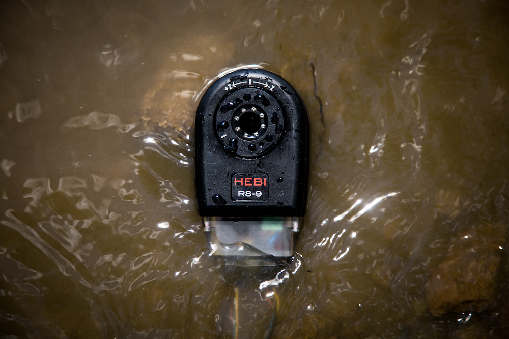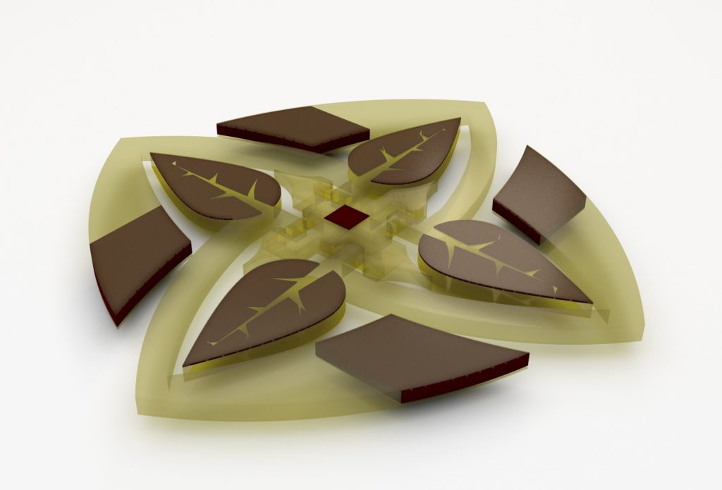
An automated system developed by MIT researchers designs and 3D prints complex robotic parts called actuators that are optimized according to an enormous number of specifications. Credit: Subramanian Sundaram
CAMBRIDGE, Mass. — An automated system developed by researchers at the Massachusetts Institute of Technology designs and 3D prints complex robotic actuators that are optimized according to an enormous number of specifications. In short, the system does automatically what is virtually impossible for humans to do by hand.
In a paper published in Science Advances, the researchers demonstrated the system by fabricating actuators that show different black-and-white images at different angles. One actuator, for instance, portrays a Vincent van Gogh portrait when laid flat. When it’s activated, it tilts at an angle and displays the famous Edvard Munch painting “The Scream.”
The actuators are made from a patchwork of three different materials, each with a different light or dark color and a property — such as flexibility and magnetization — that controls the actuator’s angle in response to a control signal. Software first breaks down the actuator design into millions of three-dimensional pixels, or “voxels,” that can each be filled with any of the materials.
Then, it runs millions of simulations, filling different voxels with different materials. Eventually, it lands on the optimal placement of each material in each voxel to generate two different images at two different angles. A custom 3D printer then fabricates the actuator by dropping the right material into the right voxel, layer by layer.
“Our ultimate goal is to automatically find an optimal design for any problem, and then use the output of our optimized design to fabricate it,” said first author Subramanian Sundaram, Ph.D. ’18, a former graduate student in MIT’s Computer Science and Artificial Intelligence Laboratory (CSAIL). “We go from selecting the printing materials, to finding the optimal design, to fabricating the final product in almost a completely automated way.”
New robotic actuators mimic biology for efficiency
The shifting images demonstrates what the system can do. But actuators optimized for appearance and function could also be used for biomimicry in robotics. For instance, other researchers are designing underwater robotic skins with actuator arrays meant to mimic denticles on shark skin. Denticles collectively deform to decrease drag for faster, quieter swimming.
“You can imagine underwater robots having whole arrays of actuators coating the surface of their skins, which can be optimized for drag and turning efficiently, and so on,” Sundaram said.
Joining Sundaram on the paper were Melina Skouras, a former MIT postdoc; David S. Kim, a former researcher in the Computational Fabrication Group; Louise van den Heuvel ’14, SM ’16; and Wojciech Matusik, an MIT associate professor in electrical engineering and computer science and head of the Computational Fabrication Group.
Navigating the ‘combinatorial explosion’
Robotic actuators are becoming increasingly complex. Depending on the application, they must be optimized for weight, efficiency, appearance, flexibility, power consumption, and various other functions and performance metrics. Generally, experts manually calculate all those parameters to find an optimal design.
Adding to that complexity, new 3D-printing techniques can now use multiple materials to create one product. That means the design’s dimensionality becomes incredibly high
“What you’re left with is what’s called a ‘combinatorial explosion,’ where you essentially have so many combinations of materials and properties that you don’t have a chance to evaluate every combination to create an optimal structure,” Sundaram said.
The researchers first customized three polymer materials with specific properties they needed to build their robotic actuators: color, magnetization, and rigidity. They ultimately produced a near-transparent rigid material, an opaque flexible material used as a hinge, and a brown nanoparticle material that responds to a magnetic signal. They plugged all that characterization data into a property library.
The system takes as input grayscale image examples — such as the flat actuator that displays the Van Gogh portrait but tilts at an exact angle to show “The Scream.” It basically executes a complex form of trial and error that’s somewhat like rearranging a Rubik’s Cube, but in this case around 5.5 million voxels are iteratively reconfigured to match an image and meet a measured angle.
Initially, the system draws from the property library to randomly assign different materials to different voxels. Then, it runs a simulation to see if that arrangement portrays the two target images, straight on and at an angle. If not, it gets an error signal. That signal lets it know which voxels are on the mark and which should be changed.
Adding, removing, and shifting around brown magnetic voxels, for instance, will change the actuator’s angle when a magnetic field is applied. But, the system also has to consider how aligning those brown voxels will affect the image.
Credit: Subramanian Sundaram
Voxel by voxel
To compute the actuator’s appearances at each iteration, the researchers adopted a computer graphics technique called “ray-tracing,” which simulates the path of light interacting with objects. Simulated light beams shoot through the actuator at each column of voxels.
Actuators can be fabricated with more than 100 voxel layers. Columns can contain more than 100 voxels, with different sequences of the materials that radiate a different shade of gray when flat or at an angle.
When the actuator is flat, for instance, the light beam may shine down on a column containing many brown voxels, producing a dark tone. But when the actuator tilts, the beam will shine on misaligned voxels. Brown voxels may shift away from the beam, while more clear voxels may shift into the beam, producing a lighter tone.
The system uses that technique to align dark and light voxel columns where they need to be in the flat and angled image. After 100 million or more iterations, and anywhere from a few to dozens of hours, the system will find an arrangement that fits the target images.
“We’re comparing what that [voxel column] looks like when it’s flat or when it’s titled, to match the target images,” Sundaram said. “If not, you can swap, say, a clear voxel with a brown one. If that’s an improvement, we keep this new suggestion and make other changes over and over again.”
To fabricate the actuators, the researchers built a custom 3-D printer that uses a technique called “drop-on-demand.” Tubs of the three materials are connected to print heads with hundreds of nozzles that can be individually controlled. The printer fires a 30-micron-sized droplet of the designated material into its respective voxel location. Once the droplet lands on the substrate, it’s solidified. In that way, the printer builds an object, layer by layer.
The work could be used as a stepping stone for designing larger structures, such as airplane wings, Sundaram says. Researchers, for instance, have similarly started breaking down airplane wings into smaller voxel-like blocks to optimize their designs for weight and lift, and other metrics.
“We’re not yet able to print wings or anything on that scale, or with those materials,” said Sundaram. “But I think this is a first step toward that goal.”
Editor’s note: This article republished with permission from MIT News.
The post Automated system from MIT generates robotic actuators for novel tasks appeared first on The Robot Report.