Step motors and drives from Applied Motion Products
The mistakes outlined here by Eric Rice, national marketing director at Applied Motion Products, have been corrected countless times by thousands of step motor users around the world. Avoid these mistakes with the presented solutions — and make your next application a successful one.
Step motors offer the automation industry a cost-effective and simple method to digitally control motion in a wide range of applications — including packaging equipment, 3D printers, material handling and sorting lines, bench-top CNC machines, and more. They serve as critical components of many rotary and linear positioning axes.
The cost-performance benefits of step motors lie in their simplicity and their ability to position accurately in open-loop control schemes, without any feedback from the motor to the controller. Getting the optimal performance benefits of an open-loop stepper system requires understanding how to specify and install a step motor into an application. Following are six common mistakes that step motor users, both novice and experienced, can easily avoid.
1. ‘The torque spec of the motor is higher than what I’m seeing in practice.’
After calculating the torque required to move the load in an application, a user selects a step motor based on (1) the holding torque specification of the motor or (2) the speed-torque curve. Once mounted and coupled to the load, the motor doesn’t produce the amount of expected torque.
The first mistake is using the holding torque as a measure of performance to specify the step motor. Holding torque defines the torque a motor produces when maintaining a position and not moving. It is generally a poor indicator of the torque the motor produces when moving.
When a step motor starts moving, the produced torque falls precipitously from the holding torque value, even after just a few rpms. As speed increases, the torque falls further. For this reason, don’t select a motor based on holding torque alone. Instead, refer to published speed-torque curves.

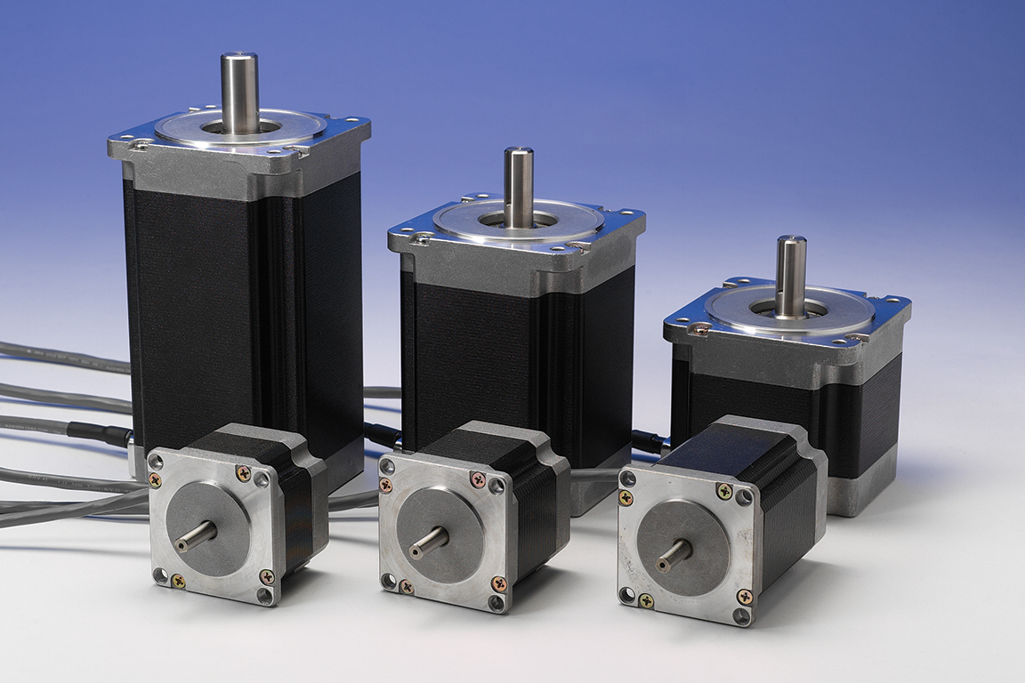
Shown here are step motors from Applied Motion Products with various stack lengths.
The second mistake is failing to understand the nature of speed-torque curves. A speed-torque curve represents the torque at which the step motor stalls. When a motor stalls, the rotor loses synchronization with the stator, and the shaft stops turning.
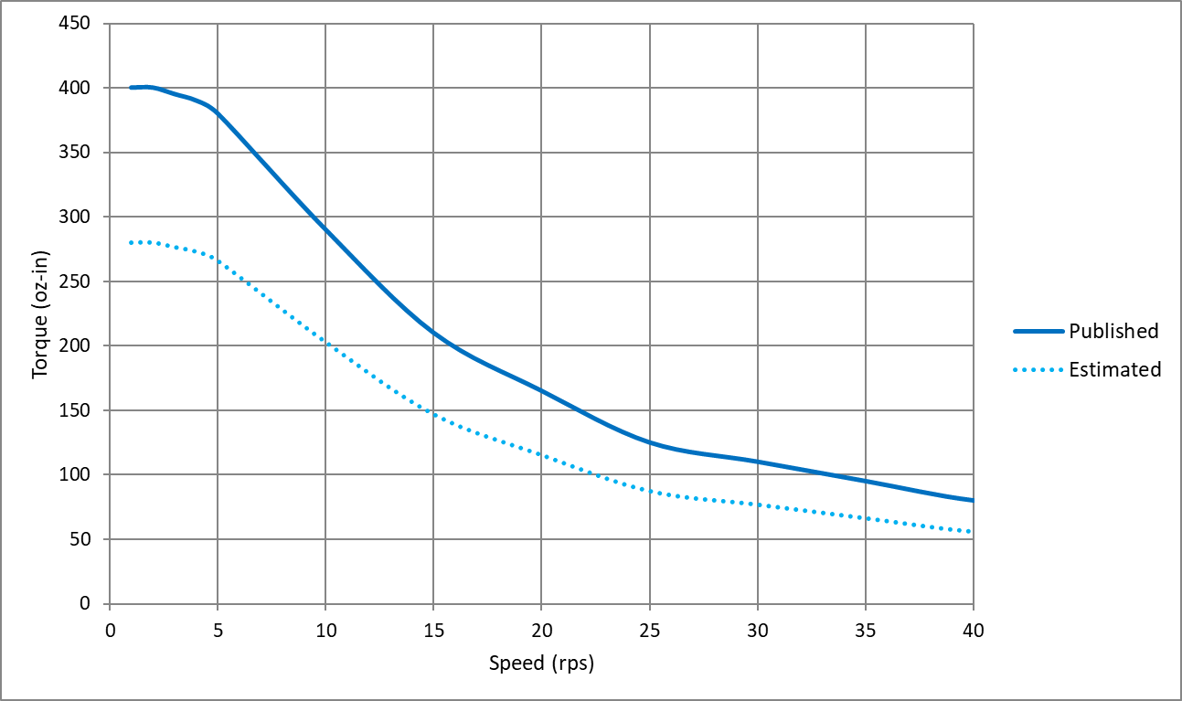
To ensure the step motor continues to turn and provides enough torque to move the load, evaluate the speed-torque curves by estimating a margin of safety. A simple way to do this is by imagining a line parallel to the speed-torque curve at roughly 1/2 to 2/3 the height of the published curve. This imaginary line represents an amount of torque that a step motor can reliably produce with minimal risk of stalling. See Figure 1 below for more on this.

Figure 1 — typical speed-torque curve of a step motor. In published data from the manufacturer, only the solid line is shown, which indicates stall torque versus speed. The user must estimate a usable torque range as shown by the dashed line.
2. ‘The step motor is so hot; there must be something wrong with it.’
Step motors are designed to run hot. The most common insulation class used in step motors is Class B, which is rated for operation up to 130° C. This means that the surface temperature of a step motor can reach 90° C or more before failing. This temperature is much hotter than a person could touch without burning the skin. For this reason, mount motors away from areas with a high chance of human contact.
Step motors are designed to run at high temperatures because of their use in open-loop control systems. Because an open-loop step motor operates without any current feedback (or velocity or position feedback), the current supplied by the drive is constant, regardless of the torque demand.
To get the most torque from step motors, manufacturers specify them with the Class B insulation in mind; so, current ratings are designed to maximize torque output without overheating. The end result is that step motors produce a lot of torque … but they also get quite hot in doing so.
3. ‘Can I use a 12V power supply to power my motor and drive?’
For any kind of electric motor, not just step motors, the supply voltage is directly related to motor speed. As higher voltages are supplied to the system, the motor achieves higher speeds. The rated supply voltage specified for servo and DC motors correspond to other rated specifications including speed, torque, and power.
If a step motor is specified with a rated voltage, it is typically no more than the motor’s winding resistance times the rated current. This is useful for producing holding torque but of very little use when the step motor moves.
Like all electric motors, when the shaft starts moving, the step motor produces a back EMF (BEMF) voltage that impedes the current flowing into the windings. To produce usable torque, the supply voltage must be substantially higher than the BEMF. Because no hard and fast rules exist for how high to specify the supply voltage, users should review the published speed-torque curves for a given step motor, drive, and power supply combination.
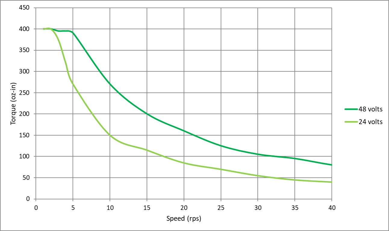
The supply voltage specified in the speed-torque curve is essential information. If ignored, say by using a 12-V supply when the published curve uses a 48-V supply, the motor won’t reach the expected torque. See Figure 2 below.

Figure 2 — two speed-torque curves of the same step motor and drive combination. Only the power supply voltage is different. The dark green line shows stall torque with a 48-V power supply. The light green line shows stall torque with a 24-V supply. A 12-V supply would spur an even lower curve.
4. ‘Can’t I run this step motor with a couple of PLC outputs? Why do a need a drive?’
Two-phase stepper drives use a set of eight transistors connected to form an H-bridge. Creating an equivalent H-bridge from PLC outputs would require eight outputs. Some two-phase step motors with six lead wires are driven with as few as four transistors. For these, you could use four PLC outputs to rotate a step motor forward and backward. However, a stepper drive does much more than simply sequence the transistors in the H-bridge.
Stepper drives regulate the current in each phase of the motor using PWM switching of the bus voltage. As noted in the previous section on voltage, the supply voltage must be high enough to overcome BEMF and produce torque at speed.
Stepper drives with microstepping capabilities further refine the PWM switching logic to ratio the current in each phase according to a sine wave, getting finer positioning than a step motor’s basic step angle. Moving beyond the most basic stepper drives, those that have trajectory generators on board can automatically ramp the motor speed up and down according to preset acceleration and deceleration rates.
Using PLC outputs to drive a step motor could be a neat project for someone interested in dissecting how step motors work. For any serious motion-control project, you’ll want a proper drive.
5. ‘The motor is so noisy … there must be something wrong with it.’
Every time a step motor takes a step, it generates a little bit of ringing noise as the rotor settles into position (think of the classic mass on a spring). The ringing is the motor’s natural resonant frequency, which is based on the motor construction. The natural resonant frequency is amplified when the frequency of motor steps approaches or equals it.
This noise is most pronounced when the step motor is driven in full step sequence (the lowest resolution available; equal to the motor’s step angle) and at low speeds, typically in the range of 1 to 5 revolutions per second.
The question of noise most often arises when a user tests a step motor for the first time with the motor unmounted and uncoupled to any load. In this scenario, the motor is free to resonate as much as it likes without anything to damp the resonance.
Fortunately, a few easy steps can mitigate the resonance:
- Add mechanical damping to the system by mounting the motor and coupling the motor shaft to a load. Coupling the shaft to a load adds some amount of inertia or friction to the system … and that in turn alters or damps the motor’s natural resonant frequency.
- Reduce the step angle with microstepping. When microstepping, the step angle is much smaller with each step and the natural resonant frequency is excited less.
If neither of these steps works, consider using a stepper drive with an anti-resonance algorithm built into its current control logic.
6. ‘I need an encoder to run a step motor, right?’
No, an encoder is not required to run a step motor in open-loop control. Step motors are the only type of brushless DC motor that accurately and repeatedly position a load using open-loop control. Other motors need some type of position feedback. Open-loop control works well when:
- Motion tasks are the same over time.
- The load doesn’t change.
- The required speeds are relatively low.
- Failure to complete the motion task does not result in critical or dangerous machine failure.
If the application doesn’t meet the stated criteria, consider introducing feedback into the system to permit some level of closed-loop control. Adding an encoder to a step motor system offers benefits ranging from basic functions that are essentially open-loop control but with subtle, effective improvements, to fully closed-loop control where the step motor operates as part of a servo control system. Contact your step motor and drive supplier for information on the range of feedback and closed-loop control options they offer.

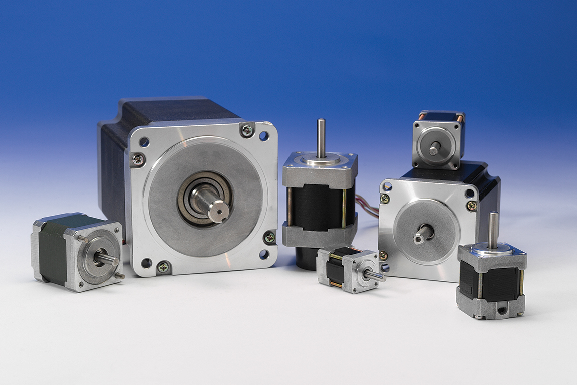
Applied Motion Products step motors come in a wide range of frame sizes — from NEMA 8 to NEMA 42 and beyond.
Editor’s note: This article originally ran on Design World, a sibling site of The Robot Report.
The post 6 common step motor mistakes to avoid in automation applications appeared first on The Robot Report.