First sea trials of a revolutionary new undersea robot
In late June researchers from MBARI joined engineers from Woods Hole Oceanographic Institution (WHOI) to test a new breed of undersea robot ...
Welcome to robotics research and development
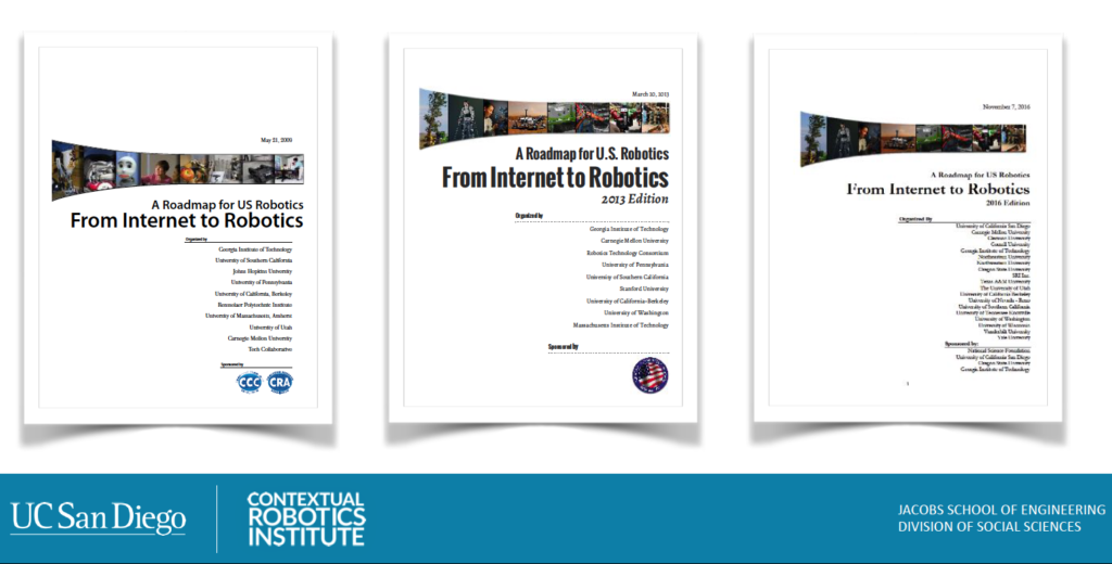
The U.S. National Robotics Roadmap was first created 10 years ago. Since then, government agencies, universities, and companies have used it as a reference for where robotics is going. The first roadmap was published in 2009 and then revised in 2013 and 2016. The objective is to publish the fourth version of the roadmap by summer 2020.
The team developing the U.S. National Robotics Roadmap has put out a call to engage about 150 to 200 people from academia and industry to ensure that it is representative of the robotics community’s view of the future. The roadmap will cover manufacturing, service, medical, first-responder, and space robotics.
The revised roadmap will also include considerations related to ethics and workforce. It will cover emerging applications, the key challenges to progress, and what research and development is needed.
Three one-and-a-half-day workshops will be organized for community input to the roadmap. The workshops will take place as follows:
Participation in these workshops will be by invitation only. To participate, please submit a white paper/position statement of a maximum length of 1.5 pages. What are key use cases for robotics in a five-to-10-year perspective, what are key limitations, and what R&D is needed in that time frame? The white paper can address all three aspects or focus on one of them. The white paper must include the following information:
Please submit the white paper as regular text or as a PDF file. Statements that are too long will be ignored. Position papers that only focus on current research are not appropriate. A white paper should present a future vision and not merely discuss state of the art.
White papers should be submitted by end of the day Aug. 15, 2019, to roadmapping@robotics-vo.org. Late submissions may not be considered. We will evaluate submitted white papers by Aug. 18 and select people for the workshops by Aug. 19.
The workshop reports will be used as the basis for a synthesis of a new roadmap. The nominal timeline is:
If you have any questions about the process, the scope, etc., please send e-mail to Henrik I Christensen at hichristensen@eng.ucsd.edu.
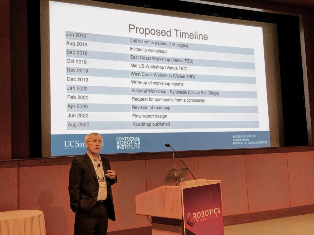
Henrik I Christensen spoke at the Robotics Summit & Expo in Boston.
Editor’s note: Christensen, Qualcomm Chancellor’s Chair of Robot Systems at the University of California San Diego and co-founder of Robust AI, delivered a keynote address at last month’s Robotics Summit & Expo, produced by The Robot Report.
The post U.S. Robotics Roadmap calls for white papers for revision appeared first on The Robot Report.
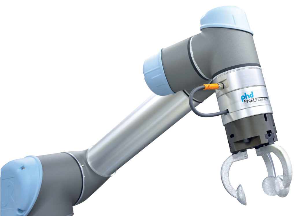
PneuConnect with GRT gripper on a UR cobot. Source: PHD
PHD Inc. this month added three products to its line of grippers and accessories for industrial automation. They are intended to help robots grip large objects, make positioning and programming easy for maximum efficiency, and facilitate machine tending. PHD’s products are designed to work with collaborative robot arms, or cobots, from Universal Robots A/S.
Fort Wayne, In.-based PHD said it sells grippers, linear slides, and the widest range of long-life, robust actuators in the industry. It also offers engineering software and Internet-based tools to save design time, support from factory-trained application and industry specialists, and rapid product delivery.
The company has added a 300mm (11.81 in.) jaw-travel model of its Series GRR high-capacity pneumatic grippers. These parallel grippers are designed to provide high grip force, five long-jaw travels, and high loads.
Because the Guardian grippers can withstand high impact and shock loads, they are suitable for applications such as small engine block manufacturing, automotive wheel-rim manufacturing, and foundry applications, said PHD.
Also available is the Series EGRR high-capacity electric parallel grippers, which offer many of the same benefits as the pneumatic design.
PHD also announced the release of Pneu-Connext X2 kits with dual grippers. They can be mounted to UR cobots for maximum efficiency in automation performance.
The Pneu-Connect X2 includes PHD’s Freedrive feature, which interfaces with UR cobots for easy positioning and programming. The kits come in the following standard combinations:
Contact PHD for other gripper combinations.
The Pneu-Connect® X2 includes the following features, said PHD:
Download the Pneu-Connect catalog for more information.
PHD’s transition plate allows a Universal Robot arm to be directly attached to the new PHD Series ESU electric belt-driven linear actuator. The company said it offers a transition plate for each size of UR arm, “taking machine tending to a whole new level.”
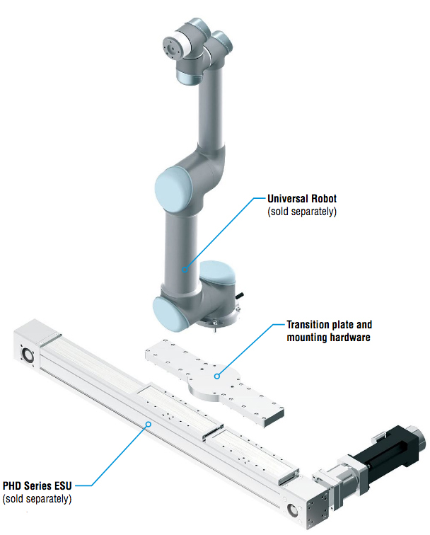
This transition plate provides a seventh axis for UR arms with the ESU linear actuator. Source: PHD
With a cataloged stroke of up to 5500mm (216.53 in.), users can increase the working area of a UR10 arm by 10 times.
The post PHD adds gripper options, transition plate to product line appeared first on The Robot Report.
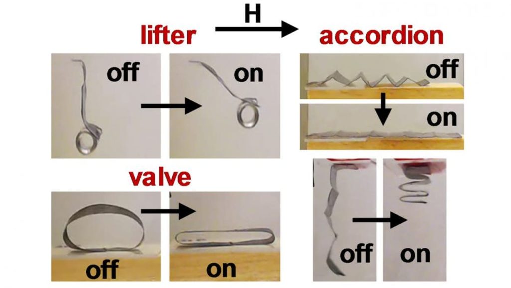
Researchers from North Carolina State University and Elon University have developed a technique that allows them to remotely control the movement of soft robots, lock them into position for as long as needed, and later reconfigure the robots into new shapes. The technique relies on light and magnetic fields.
“We’re particularly excited about the reconfigurability,” said Joe Tracy, a professor of materials science and engineering at NC State and corresponding author of a paper on the work. “By engineering the properties of the material, we can control the soft robot’s movement remotely; we can get it to hold a given shape; we can then return the robot to its original shape or further modify its movement; and we can do this repeatedly. All of those things are valuable, in terms of this technology’s utility in biomedical or aerospace applications.”
For this work, the researchers used soft robots made of a polymer embedded with magnetic iron microparticles. Under normal conditions, the material is relatively stiff and holds its shape.
However, researchers can heat up the material using light from a light-emitting diode (LED), which makes the polymer pliable. Once pliable, researchers demonstrated that they could control the shape of the robot remotely by applying a magnetic field. After forming the desired shape, researchers could remove the LED light, allowing the robot to resume its original stiffness — effectively locking the shape in place.
By applying the light a second time and removing the magnetic field, the researchers could get the soft robots to return to their original shapes. Or they could apply the light again and manipulate the magnetic field to move the robots or get them to assume new shapes.
In experimental testing, the researchers demonstrated that the soft robots could be used to form “grabbers” for lifting and transporting objects. The soft robots could also be used as cantilevers, or folded into “flowers” with petals that bend in different directions.
“We are not limited to binary configurations, such as a grabber being either open or closed,” said Jessica Liu, first author of the paper and a Ph.D. student at NC State. “We can control the light to ensure that a robot will hold its shape at any point.”
Iron microparticles can be used to make soft robots move. Source: North Carolina State University
In addition, the researchers developed a computational model that can be used to streamline the soft robot design process. The model allows them to fine-tune a robot’s shape, polymer thickness, the abundance of iron microparticles in the polymer, and the size and direction of the required magnetic field before constructing a prototype to accomplish a specific task.
“Next steps include optimizing the polymer for different applications,” Tracy said. “For example, engineering polymers that respond at different temperatures in order to meet the needs of specific applications.”
The paper, “Photothermally and Magnetically Controlled Reconfiguration of Polymer Composites for Soft Robotics,” appears in the journal Science Advances. In addition Liu as first author, the paper was co-authored by Jonathan Gillen, a former undergraduate at NC State; Sumeet Mishra, a former Ph.D. student at NC State; and Benjamin Evans, an associate professor of physics at Elon University.
The work was done with support from the National Science Foundation (NSF) under grants CMMI-1663416 and CMMI-1662641. The work was also supported by the Research Triangle MRSEC, which is funded by NSF under grant DMR-1121107; and by NC State’s Analytical Instrumentation Facility and the Duke University Shared Materials Instrumentation Facility, which are supported by the State of North Carolina and NSF grant ECCS-1542015.
The post Soft robots controlled by magnets, light in new research appeared first on The Robot Report.
An international team of scientists has developed an ultra-thin, wearable electronic device that facilitates smooth communication between humans and machines. The researchers said the new device is easy to manufacture and imperceptible when worn. It could be applied to human skin to capture various types of physical data for better health monitoring and early disease detection, or it could enable robots to perform specific tasks in response to physical cues from humans.
Wearable human-machine interfaces have had challenges — some are made from rigid electronic chips and sensors that are uncomfortable and restrict the body’s motion, while others consist of softer, more wearable elastic materials but suffer from slow response times.
While researchers have developed thin inorganic materials that wrinkle and bend, the challenge remains to develop wearable devices with multiple functions that enable smooth communication between humans and machines.
The team that wrote the paper included Kyoseung Sim, Zhoulyu Rao; Faheem Ershad; Jianming Lei, Anish Thukral, Jie Chen, and Cunjiang Yu at University of Houston. It also included Zhanan Zou and Jianling Xiao at University of Colorado, Boulder, and Qing-An Huang at Southeast University in Nanjing, China.
Kyoseung Sim and company have designed a nanomembrane made from indium zinc oxide using a chemical processing approach that allows them to tune the material’s texture and surface properties. The resulting devices were only 3 to 4 micrometers thick, and snake-shaped, properties that allow them to stretch and remain unnoticed by the wearer.
When worn by humans, the devices could collect signals from muscle and use them to directly guide a robot, enabling the user to feel what the robot hand experienced. The devices maintain their function when human skin is stretched or compressed.

Soft, unnoticeable, multifunctional, electronics-based, wearable human-machine interface devices. Credit: Cunjiang Yu
The researchers also found that sensors made from this nanomembrane material could be designed to monitor UV exposure (to mitigate skin disease risk) or to detect skin temperature (to provide early medical warnings), while still functioning well under strain.
Editor’s note: This month’s print issue of The Robot Report, which is distributed with Design World, focuses on exoskeletons. It will be available soon.
The post Wearable device could improve communication between humans, robots appeared first on The Robot Report.
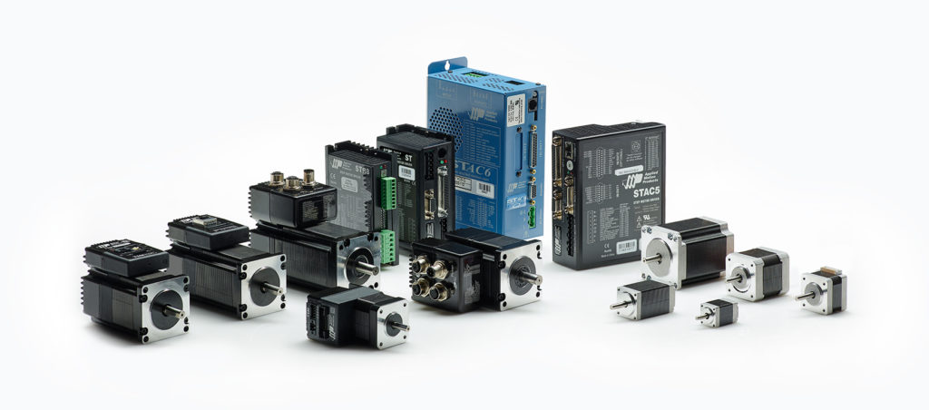
Step motors and drives from Applied Motion Products
The mistakes outlined here by Eric Rice, national marketing director at Applied Motion Products, have been corrected countless times by thousands of step motor users around the world. Avoid these mistakes with the presented solutions — and make your next application a successful one.
Step motors offer the automation industry a cost-effective and simple method to digitally control motion in a wide range of applications — including packaging equipment, 3D printers, material handling and sorting lines, bench-top CNC machines, and more. They serve as critical components of many rotary and linear positioning axes.
The cost-performance benefits of step motors lie in their simplicity and their ability to position accurately in open-loop control schemes, without any feedback from the motor to the controller. Getting the optimal performance benefits of an open-loop stepper system requires understanding how to specify and install a step motor into an application. Following are six common mistakes that step motor users, both novice and experienced, can easily avoid.
After calculating the torque required to move the load in an application, a user selects a step motor based on (1) the holding torque specification of the motor or (2) the speed-torque curve. Once mounted and coupled to the load, the motor doesn’t produce the amount of expected torque.
The first mistake is using the holding torque as a measure of performance to specify the step motor. Holding torque defines the torque a motor produces when maintaining a position and not moving. It is generally a poor indicator of the torque the motor produces when moving.
When a step motor starts moving, the produced torque falls precipitously from the holding torque value, even after just a few rpms. As speed increases, the torque falls further. For this reason, don’t select a motor based on holding torque alone. Instead, refer to published speed-torque curves.
Shown here are step motors from Applied Motion Products with various stack lengths.
The second mistake is failing to understand the nature of speed-torque curves. A speed-torque curve represents the torque at which the step motor stalls. When a motor stalls, the rotor loses synchronization with the stator, and the shaft stops turning.
To ensure the step motor continues to turn and provides enough torque to move the load, evaluate the speed-torque curves by estimating a margin of safety. A simple way to do this is by imagining a line parallel to the speed-torque curve at roughly 1/2 to 2/3 the height of the published curve. This imaginary line represents an amount of torque that a step motor can reliably produce with minimal risk of stalling. See Figure 1 below for more on this.
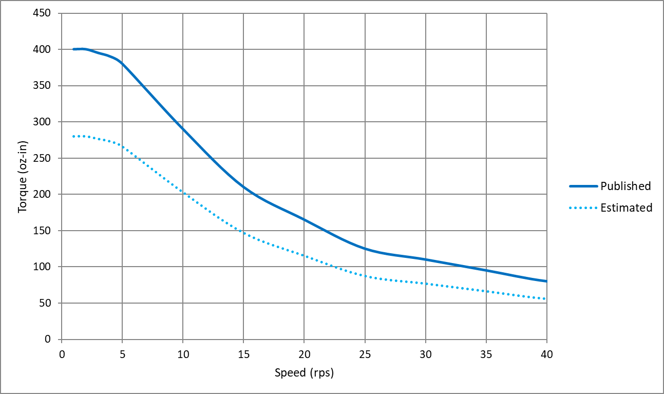
Figure 1 — typical speed-torque curve of a step motor. In published data from the manufacturer, only the solid line is shown, which indicates stall torque versus speed. The user must estimate a usable torque range as shown by the dashed line.
Step motors are designed to run hot. The most common insulation class used in step motors is Class B, which is rated for operation up to 130° C. This means that the surface temperature of a step motor can reach 90° C or more before failing. This temperature is much hotter than a person could touch without burning the skin. For this reason, mount motors away from areas with a high chance of human contact.
Step motors are designed to run at high temperatures because of their use in open-loop control systems. Because an open-loop step motor operates without any current feedback (or velocity or position feedback), the current supplied by the drive is constant, regardless of the torque demand.
To get the most torque from step motors, manufacturers specify them with the Class B insulation in mind; so, current ratings are designed to maximize torque output without overheating. The end result is that step motors produce a lot of torque … but they also get quite hot in doing so.
For any kind of electric motor, not just step motors, the supply voltage is directly related to motor speed. As higher voltages are supplied to the system, the motor achieves higher speeds. The rated supply voltage specified for servo and DC motors correspond to other rated specifications including speed, torque, and power.
If a step motor is specified with a rated voltage, it is typically no more than the motor’s winding resistance times the rated current. This is useful for producing holding torque but of very little use when the step motor moves.
Like all electric motors, when the shaft starts moving, the step motor produces a back EMF (BEMF) voltage that impedes the current flowing into the windings. To produce usable torque, the supply voltage must be substantially higher than the BEMF. Because no hard and fast rules exist for how high to specify the supply voltage, users should review the published speed-torque curves for a given step motor, drive, and power supply combination.
The supply voltage specified in the speed-torque curve is essential information. If ignored, say by using a 12-V supply when the published curve uses a 48-V supply, the motor won’t reach the expected torque. See Figure 2 below.
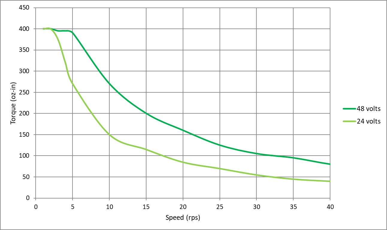
Figure 2 — two speed-torque curves of the same step motor and drive combination. Only the power supply voltage is different. The dark green line shows stall torque with a 48-V power supply. The light green line shows stall torque with a 24-V supply. A 12-V supply would spur an even lower curve.
Two-phase stepper drives use a set of eight transistors connected to form an H-bridge. Creating an equivalent H-bridge from PLC outputs would require eight outputs. Some two-phase step motors with six lead wires are driven with as few as four transistors. For these, you could use four PLC outputs to rotate a step motor forward and backward. However, a stepper drive does much more than simply sequence the transistors in the H-bridge.
Stepper drives regulate the current in each phase of the motor using PWM switching of the bus voltage. As noted in the previous section on voltage, the supply voltage must be high enough to overcome BEMF and produce torque at speed.
Stepper drives with microstepping capabilities further refine the PWM switching logic to ratio the current in each phase according to a sine wave, getting finer positioning than a step motor’s basic step angle. Moving beyond the most basic stepper drives, those that have trajectory generators on board can automatically ramp the motor speed up and down according to preset acceleration and deceleration rates.
Using PLC outputs to drive a step motor could be a neat project for someone interested in dissecting how step motors work. For any serious motion-control project, you’ll want a proper drive.
Every time a step motor takes a step, it generates a little bit of ringing noise as the rotor settles into position (think of the classic mass on a spring). The ringing is the motor’s natural resonant frequency, which is based on the motor construction. The natural resonant frequency is amplified when the frequency of motor steps approaches or equals it.
This noise is most pronounced when the step motor is driven in full step sequence (the lowest resolution available; equal to the motor’s step angle) and at low speeds, typically in the range of 1 to 5 revolutions per second.
The question of noise most often arises when a user tests a step motor for the first time with the motor unmounted and uncoupled to any load. In this scenario, the motor is free to resonate as much as it likes without anything to damp the resonance.
Fortunately, a few easy steps can mitigate the resonance:
If neither of these steps works, consider using a stepper drive with an anti-resonance algorithm built into its current control logic.
No, an encoder is not required to run a step motor in open-loop control. Step motors are the only type of brushless DC motor that accurately and repeatedly position a load using open-loop control. Other motors need some type of position feedback. Open-loop control works well when:
If the application doesn’t meet the stated criteria, consider introducing feedback into the system to permit some level of closed-loop control. Adding an encoder to a step motor system offers benefits ranging from basic functions that are essentially open-loop control but with subtle, effective improvements, to fully closed-loop control where the step motor operates as part of a servo control system. Contact your step motor and drive supplier for information on the range of feedback and closed-loop control options they offer.
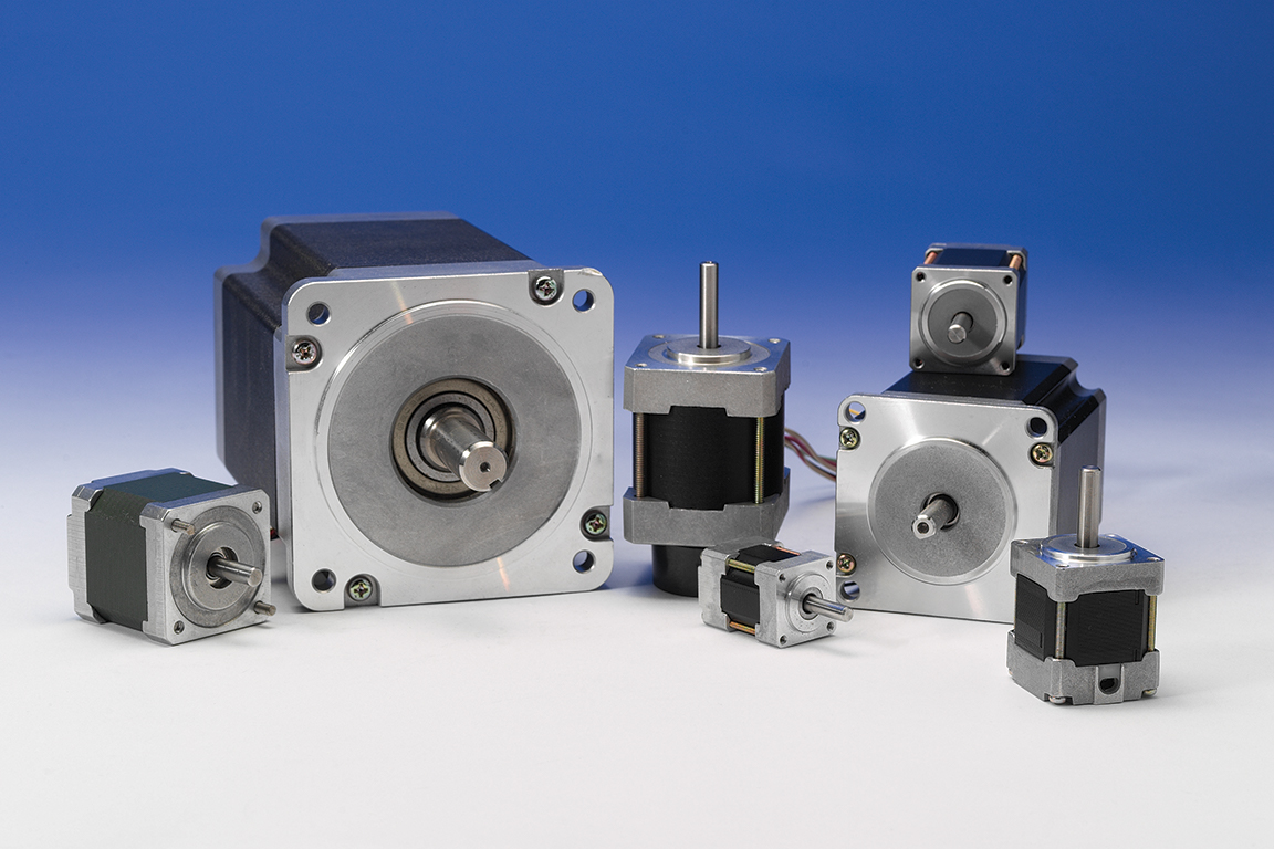
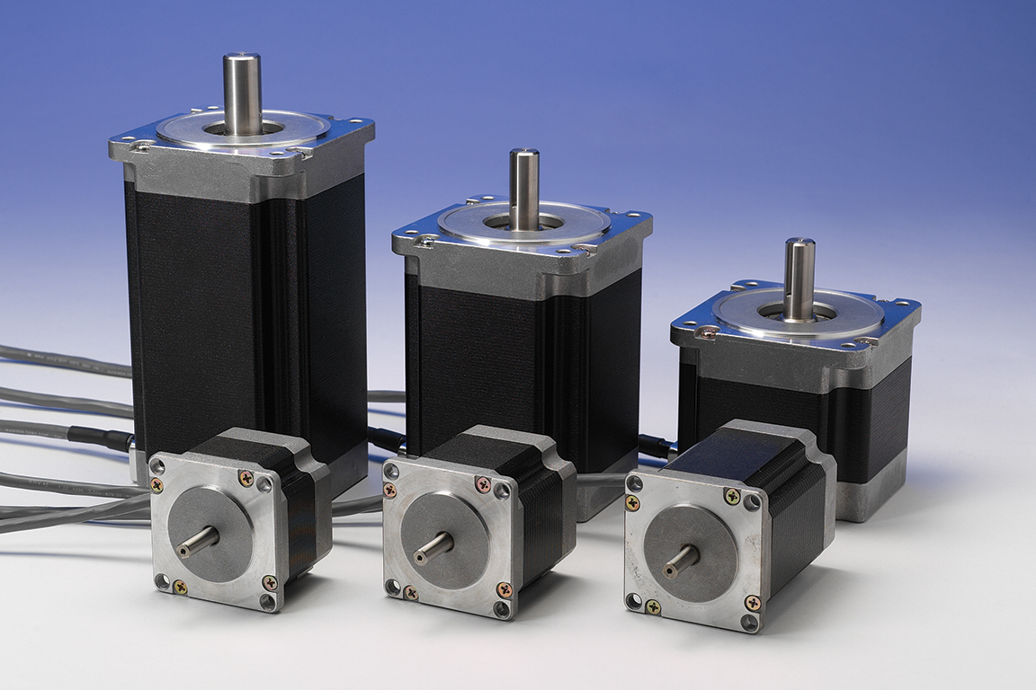
Applied Motion Products step motors come in a wide range of frame sizes — from NEMA 8 to NEMA 42 and beyond.
Editor’s note: This article originally ran on Design World, a sibling site of The Robot Report.
The post 6 common step motor mistakes to avoid in automation applications appeared first on The Robot Report.
If the sight of a skittering bug makes you squirm, you may want to look away — a new insect-sized robot created by researchers at the University of California, Berkeley, can scurry across the floor at nearly the speed of a darting cockroach. And it’s nearly as hardy as a roach is. Try to squash this robot under your foot, and more than likely, it will just keep going.
“Most of the robots at this particular small scale are very fragile. If you step on them, you pretty much destroy the robot,” said Liwei Lin, a professor of mechanical engineering at UC Berkeley and senior author of a new study that describes the robot. “We found that if we put weight on our robot, it still more or less functions.”
Small-scale robots like these could be advantageous in search-and-rescue missions, squeezing and squishing into places where dogs or humans can’t fit, or where it may be too dangerous for them to go, said Yichuan Wu, first author of the paper, who completed the work as a graduate student in mechanical engineering at UC Berkeley through the Tsinghua-Berkeley Shenzhen Institute partnership.
“For example, if an earthquake happens, it’s very hard for the big machines, or the big dogs, to find life underneath debris, so that’s why we need a small-sized robot that is agile and robust,” said Wu, who is now an assistant professor at the University of Electronic Science and Technology of China.
The study appears this week in the journal Science Robotics.
The robot, which is about the size of a large postage stamp, is made of a thin sheet of a piezoelectric material called polyvinylidene fluoride, or PVDF. Piezoelectric materials are unique, in that applying electric voltage to them causes the materials to expand or contract.
The robot is built of a layered material that bends and straightens when AC voltage is applied, causing it to spring forward in a “leapfrogging” motion. Credit: UC Berkeley video and photo by Stephen McNally
The researchers coated the PVDF in a layer of an elastic polymer, which causes the entire sheet to bend, instead of to expand or contract. They then added a front leg so that, as the material bends and straightens under an electric field, the oscillations propel the device forward in a “leapfrogging” motion.
The resulting robot may be simple to look at, but it has some remarkable abilities. It can sail along the ground at a speed of 20 body lengths per second, a rate comparable to that of a roach and reported to be the fastest pace among insect-scale robots. It can zip through tubes, climb small slopes, and carry small loads, such as a peanut.
Perhaps most impressively, the robot, which weighs less than one tenth of a gram, can withstand a weight of around 60kg [132 lb.] — about the weight of an average human — which is approximately 1 million times the weight of the robot.
“People may have experienced that, if you step on the cockroach, you may have to grind it up a little bit, otherwise the cockroach may still survive and run away,” Lin said. “Somebody stepping on our robot is applying an extraordinarily large weight, but [the robot] still works, it still functions. So, in that particular sense, it’s very similar to a cockroach.”
The robot is currently “tethered” to a thin wire that carries an electric voltage that drives the oscillations. The team is experimenting with adding a battery so the roach robot can roam independently. They are also working to add gas sensors and are improving the design of the robot so it can be steered around obstacles.
Co-authors of the paper include Justin K. Yim, Zhichun Shao, Mingjing Qi, Junwen Zhong, Zihao Luo, Ronald S. Fearing and Robert J. Full of UC Berkeley, Xiaojun Yan of Beihang University and Jiaming Liang, Min Zhang and Xiaohao Wang of Tsinghua University.
This work is supported in part by the Berkeley Sensor and Actuator Center, an Industry-University Cooperation Research Center.
Editor’s note: This article republished from the University of California, Berkeley.
The post Roach-inspired robot shares insect’s speed, toughness appeared first on The Robot Report.