Sea Machines Robotics to demonstrate autonomous spill response

Sea Machines Robotics to demonstrate autonomous spill response

Source: Sea Machines Robotics

BOSTON — Sea Machines Robotics Inc. this week said it has entered into a cooperative agreement with the U.S. Department of Transportation’s Maritime Administration to demonstrate the ability of its autonomous technology in increasing the safety, response time and productivity of marine oil-spill response operations.

Sea Machines was founded in 2015 and claimed to be “the leader in pioneering autonomous control and advanced perception systems for the marine industries.” The company builds software and systems to increase the safety, efficiency, and performance of ships, workboats, and commercial vessels worldwide.

The U.S. Maritime Administration (MARAD) is an agency of the U.S. Department of Transportation that promotes waterborne transportation and its integration with other segments of the transportation system.

Preparing for oil-spill exercise

To make the on-water exercises possible, Sea Machines will install its SM300 autonomous-command system aboard a MARCO skimming vessel owned by Marine Spill Response Corp. (MSRC), a not-for-profit, U.S. Coast Guard-classified oil spill removal organization (OSRO). MSRC was formed with the Marine Preservation Association to offer oil-spill response services in accordance with the Oil Pollution Act of 1990.

Sea Machines plans to train MSRC personnel to operate its system. Then, on Aug. 21, Sea Machines and MSRC will execute simulated oil-spill recovery exercises in the harbor of Portland, Maine, before an audience of government, naval, international, environmental, and industry partners.

The response skimming vessel is manufactured by Seattle-based Kvichak Marine Industries and is equipped with a MARCO filter belt skimmer to recover oil from the surface of the water. This vessel typically operates in coastal or near-shore areas. Once installed, the SM300 will give the MSRC vessel the following new capabilities:

  • Remote autonomous control from an onshore location or secondary vessel,
  • ENC-based mission planning,
  • Autonomous waypoint tracking,
  • Autonomous grid line tracking,
  • Collaborative autonomy for multi-vessel operations,
  • Wireless remote payload control to deploy onboard boom and other response equipment, and
  • Obstacle detection and collision avoidance.

Round-the-clock response

In addition, Sea Machines said, it enables minimally manned and unmanned autonomous maritime operations. Such configurations allow operators to respond to spill events 24/7 depending on recovery conditions, even when crews are unavailable or restricted, the company said. These configurations also reduce or eliminate exposure of crewmembers to toxic fumes and other safety hazards.

“Autonomous technology has the power to not only help prevent vessel accidents that can lead to spills, but can also facilitate better preparedness; aid in safer, efficient, and effective cleanup,” said CEO Michael G. Johnson, CEO of Sea Machines. “We look forward to working closely with MARAD and MSRC in these industry-modernizing exercises.”

“Our No. 1 priority is the safety of our personnel at MSRC,” said John Swift, vice president at MSRC. “The ability to use autonomous technology — allowing response operations to continue in an environment where their safety may be at risk — furthers our mission of response preparedness.”

Sea Machines promises rapid ROI for multiple vessels

Sea Machines’ SM Series of products, which includes the SM300 and SM200, provides marine operators a new era of task-driven, computer-guided vessel control, bringing advanced autonomy within reach for small- and large-scale operations. SM products can be installed aboard existing or new-build commercial vessels with return on investment typically seen within a year.

In addition, Sea Machines has received funding from Toyota AI Ventures.

Sea Machines is also a leading developer of advanced perception and navigation assistance technology for a range of vessel types, including container ships. The company is currently testing its perception and situational awareness technology aboard one of A.P. Moller-Maersk’s new-build ice-class container ships.

The post Sea Machines Robotics to demonstrate autonomous spill response appeared first on The Robot Report.

Microrobots activated by laser pulses could deliver medicine to tumors

Targeting medical treatment to an ailing body part is a practice as old as medicine itself. Drops go into itchy eyes. A broken arm goes into a cast. But often what ails us is inside the body and is not so easy to reach. In such cases, a treatment like surgery or chemotherapy might be called for. A pair of researchers in Caltech’s Division of Engineering and Applied Science are working on an entirely new form of treatment — microrobots that can deliver drugs to specific spots inside the body while being monitored and controlled from outside the body.

“The microrobot concept is really cool because you can get micromachinery right to where you need it,” said Lihong Wang, Bren Professor of Medical Engineering and Electrical Engineering at the California Institute of Technology. “It could be drug delivery, or a predesigned microsurgery.”

The microrobots are a joint research project of Wang and Wei Gao, assistant professor of medical engineering, and are intended for treating tumors in the digestive tract.

Developing jet-powered microrobots

The microrobots consist of microscopic spheres of magnesium metal coated with thin layers of gold and parylene, a polymer that resists digestion. The layers leave a circular portion of the sphere uncovered, kind of like a porthole. The uncovered portion of the magnesium reacts with the fluids in the digestive tract, generating small bubbles. The stream of bubbles acts like a jet and propels the sphere forward until it collides with nearby tissue.

On their own, magnesium spherical microrobots that can zoom around might be interesting, but they are not especially useful. To turn them from a novelty into a vehicle for delivering medication, Wang and Gao made some modifications to them.

First, a layer of medication is sandwiched between an individual microsphere and its parylene coat. Then, to protect the microrobots from the harsh environment of the stomach, they are enveloped in microcapsules made of paraffin wax.

Laser-guided delivery

At this stage, the spheres are capable of carrying drugs, but still lack the crucial ability to deliver them to a desired location. For that, Wang and Gao use photoacoustic computed tomography (PACT), a technique developed by Wang that uses pulses of infrared laser light.

The infrared laser light diffuses through tissues and is absorbed by oxygen-carrying hemoglobin molecules in red blood cells, causing the molecules to vibrate ultrasonically. Those ultrasonic vibrations are picked up by sensors pressed against the skin. The data from those sensors is used to create images of the internal structures of the body.

Previously, Wang has shown that variations of PACT can be used to identify breast tumors, or even individual cancer cells. With respect to the microrobots, the technique has two jobs. The first is imaging. By using PACT, the researchers can find tumors in the digestive tract and also track the location of the microrobots, which show up strongly in the PACT images.

Microrobots activated by laser pulses could deliver medicine to tumors

Microrobots activated by lasers and powered by magnesium jets could deliver medicine within the human body. Source: Caltech

Once the microrobots arrive in the vicinity of the tumor, a high-power continuous-wave near-infrared laser beam is used to activate them. Because the microrobots absorb the infrared light so strongly, they briefly heat up, melting the wax capsule surrounding them, and exposing them to digestive fluids.

At that point, the microrobots’ bubble jets activate, and the microrobots begin swarming. The jets are not steerable, so the technique is sort of a shotgun approach — the microrobots will not all hit the targeted area, but many will. When they do, they stick to the surface and begin releasing their medication payload.

“These micromotors can penetrate the mucus of the digestive tract and stay there for a long time. This improves medicine delivery,” Gao says. “But because they’re made of magnesium, they’re biocompatible and biodegradable.”

Pushing the concept

Tests in animal models show that the microrobots perform as intended, but Gao and Wang say they are planning to continue pushing the research forward.

“We demonstrated the concept that you can reach the diseased area and activate the microrobots,” Gao says. “The next step is evaluating the therapeutic effect of them.”

Gao also says he would like to develop variations of the microrobots that can operate in other parts of the body, and with different types of propulsion systems.

Wang says his goal is to improve how his PACT system interacts with the microrobots. The infrared laser light it uses has some difficulty reaching into deeper parts of the body, but he says it should be possible to develop a system that can penetrate further.

The paper describing the microrobot research, titled, “A microrobotic system guided by photoacoustic tomography for targeted navigation in intestines in vivo,” appears in the July 24 issue of Science Robotics. Other co-authors include Zhiguang Wu, Lei Li, Yiran Yang (MS ’18), Yang Li, and So-Yoon Yang of Caltech; and Peng Hu of Washington University in St. Louis. Funding for the research was provided by the National Institutes of Health and Caltech’s Donna and Benjamin M. Rosen Bioengineering Center.

Editor’s note: This article republished from the California Institute of Technology.

The post Microrobots activated by laser pulses could deliver medicine to tumors appeared first on The Robot Report.

ASTM International proposes standards guide, center of excellence for exoskeletons

One of the barriers to more widespread development and adoption of exoskeletons for industrial, medical, and military use has been a lack of standards. ASTM International this month proposed a guide to provide standardized tools to assess and improve the usability and usefulness of exoskeletons and exosuits.

“Exoskeletons and exosuits can open up a world of possibilities, from helping workers perform industrial tasks while not getting overstressed, to helping stroke victims learning to walk again, to helping soldiers carry heavier rucksacks longer distances,” said Kevin Purcell, an ergonomist at the U.S. Army Public Health Center’s Aberdeen Proving Ground. “But if it doesn’t help you perform your task and/or it’s hard to use, it won’t get used.”

He added that the guide will incorporate ways to understand the attributes of exoskeletons, as well as observation methods and questionnaires to help assess an exoskeleton’s performance and safety.

“The biggest challenge in creating this standard is that exoskeletons change greatly depending on the task the exoskeleton is designed to help,” said Purcell. “For instance, an industrial exoskeleton is a totally different design from one used for medical rehabilitation. The proposed standard will need to cover all types and industries.”

According to Purcell, industrial, medical rehabilitation, and defense users will benefit most from the proposed standard, as will exoskeleton manufacturers and regulatory bodies.

The F48 committee of ASTM International, previously known as he American Society for Testing and Materials, was formed in 2017. It is currently working on the proposed exoskeleton and exosuit standard, WK68719. Six subcommittees include about 150 members, including startups, government agencies, and enterprises such as Boeing and BMW.

ASTM publishes first standards

In May, ASTM International published its first two standards documents, which are intended to provide consensus terminology (F3323) and set forth basic labeling and other informational requirements (F3358). The standards are available for purchase.

“Exoskeletons embody the technological promise of empowering humans to be all they can be,” said F48 committee member William Billotte, a physical scientist at the U.S. National Institute of Standards and Technology (NIST). “We want to make sure that labels and product information are clear, so that exoskeletons fit people properly, so that they function safely and effectively, and so that people can get the most from these innovative products.”

The committee is working on several proposed standards and welcomes more participation from members of the exoskeleton community. For example, Billotte noted that the committee seeks experts in cybersecurity due to the growing need to secure data, controls, and biometrics in many exoskeletons.

ASTM proposes standards guide, center of excellence for exoskeletons

An exoskeleton vest at a BMW plant in in Spartanburg, S.C. Source: BMW

Call for an exoskeleton center of excellence

Last month, ASTM International called for proposals for an “Exo Technologies Center of Excellence.” The winner would receive up to $250,000 per year for up to five years. Full proposals are due today, and the winner will be announced in September, said ASTM.

“Now is the right time to create a hub of collaboration among startups, companies, and other entities that are exploring how exoskeletons could support factory workers, patients, the military, and many other people,” stated ASTM International President Katharine Morgan. “We look forward to this new center serving as a catalyst for game-changing R&D, standardization, related training, partnerships, and other efforts that help the world benefit from this exciting new technology.”

The center of excellence is intended to fill knowledge gaps, provide a global hub for education and a neutral forum to discuss common challenges, and provide a library of community resources. It should also coordinate global links among stakeholders, said ASTM.

West Conshohocken, Pa.-based ASTM International said it meets World Trade Organization (WTO) principles for developing international standards. The organization’s standards are used globally in research and development, product testing, quality systems, commercial transactions, and more.

The post ASTM International proposes standards guide, center of excellence for exoskeletons appeared first on The Robot Report.

COAST Autonomous to deploy first self-driving vehicles at rail yard

PASADENA, Calif. — COAST Autonomous today announced that Harbor Rail Services of California has selected it to deploy self-driving vehicles at the Kinney County Railport in Texas.

This groundbreaking collaboration is the first deployment of self-driving vehicles at a U.S. rail yard, said the companies. Harbor Rail and COAST teams have identified a number of areas where autonomous vehicles can add value, including staff transportation, delivery of supplies and equipment, perimeter security, and lawn mowing.

COAST Autonomous is a software and technology company focused on delivering autonomous vehicle (AV) solutions at appropriate speeds for urban and campus environments. COAST said its mission is to build community by connecting people with mobility solutions that put pedestrians first and give cities back to people.

COAST has developed a full stack of AV software that includes mapping and localization, robotics and artificial intelligence, fleet management and supervision systems. Partnering with proven manufacturers, COAST said it can provide a variety of vehicles equipped with its software to offer Mobility-as-a-Service (MaaS) to cities, theme parks, campuses, airports, and other urban environments.

The company said its team has experience and expertise in all aspects of implementing and operating AV fleets while prioritizing safety and the user experience. Last year, the company conducted a demonstration in New York’s Times Square.

Harbor Rail operates railcar repair facilities across the U.S., including the Kinney County Railport (KCRP), a state-of-the-art railcar repair facility that Harbor Rail operates near the U.S.-Mexico border. KCRP is located on 470 acres of property owned by Union Pacific, the largest railroad in North America. The facility prepares railcars to meet food-grade guidelines, so they are ready to be loaded with packaged beer in Mexico and return to the U.S. with product for distribution.

COAST completes mapping, ready to begin service

COAST has completed 3D mapping of the facility, a first step in any such deployment, and the first self-driving vehicle is expected to begin service at KCRP next month.

“Through the introduction of re-designed trucks, innovative process improvements and adoption of data-driven KPIs [key performance indicators], Harbor Rail successfully reduced railcar rejections rates from 30% to 0.03% in KCRP’s first year of operations,” said Mark Myronowicz, president of Harbor Rail. “However, I am always looking for ways to improve our performance and provide an even better service for our customers.”

COAST Autonomous to deploy first self-driving vehicles at rail yard

Source: COAST Autonomous

“At a large facility like KCRP, we have many functions that I am convinced can be carried out by COAST vehicles,” Myronowicz said. “This will free up additional labor to work on railcars, make us even more efficient, help keep the facility safe at night, and even cut the grass when most of us are asleep. This is a fantastic opportunity to demonstrate Harbor Rail’s commitment to being at the forefront of innovation and customer service.”

“This is an exciting moment for COAST, and we are looking forward to working with Harbor Rail’s industry-leading team,” said David M. Hickey, chairman and CEO of COAST Autonomous. “KCRP is exactly the type of facility that will show how self-driving technology can improve efficiency and cut costs.”

“While the futuristic vision of driverless cars has grabbed most of the headlines, COAST’s team has been focused on useful mobility solutions that can actually be deployed and create tremendous value for private sites, campuses, and urban centers,” he said. “Just as railroads are often the unsung heroes of the logistics industry, COAST’s vehicles will happily go about their jobs unnoticed and quietly change the world.”

The post COAST Autonomous to deploy first self-driving vehicles at rail yard appeared first on The Robot Report.

6 common mistakes when setting up safety laser scanners


Having worked in industrial automation for most of my career, I’d like to think that I’ve built up a wealth of experience in the field of industrial safety sensors. Familiar with safety laser scanners for over a decade, I have been involved many designs and installations.

I currently work for SICK (UK) Ltd., which invented the safety laser scanner, and I continually see people making the same mistakes time and time again. This short piece highlights, in my opinion, the most common of them.

1. Installation and mounting: Thinking about safety last

If you are going to remember just one point, then this is it. Too many times have I been present at an “almost finished” machine and asked, “Right, where can I stick this scanner?”

Inevitably, what ends up happening is that blind spots (shadows created by obstacles) become apparent all over the place. This requires mechanical “bodges” and maybe even additional scanners to cover the complete area when one scanner may have been sufficient if the cell was designed properly in the first place.

In safety, designing something out is by far the most cost-effective and robust solution. If you know you are going to be using a safety laser scanner, then design it in from the beginning — it could save you a world of pain. Consider blind zones, coverage and the location of hazards.

This also goes for automated guided vehicles (AGVs). For example, the most appropriate position to completely cover an AGV is to have two scanners adjacent to each other on the corners integrated into the vehicle (See Figure 1).

Figure 1: Typical AGV scanner mounting and integration. | Credit: SICK

2. Incorrect multiple sampling values configured

An often misunderstood concept, multiple sampling indicates how often an object has to be scanned in succession before a safety laser scanner reacts. By default and out of the box, this value is usually x2 scans, which is the minimum value. However, this value may range from manufacturer to manufacturer. A higher multiple sampling value reduces the possibility that insects, weld sparks, weather (for outdoor scanners) or other particles cause the machine to shut down.

Increasing the multiple sampling can make it possible to increase a machine’s availability, but it can also have negative effects on the application. Increasing the number of samples is basically adding an OFF-Delay to the system, meaning that your protective field may need to be bigger due to the increase in the total response time.

If a scanner has a robust detection algorithm, then you shouldn’t have to increase this value too much but when this value is changed you could be creating a hazard due to lack of effectiveness of the protective device.

If the value is changed, you should make a note of the safety laser scanner’s new response time and adjust the minimum distance from the hazardous point accordingly to ensure it remains safe.

Furthermore, in vertical applications, if the multiple sampling is set too high, then it may be possible for a person to pass through the protective field without being detected — so care must be taken. For one our latest safety laser scanners, the microScan3, we provide the following advice:

Figure 2: Recommended multiple sampling values. | Credit: SICK

3. Incorrect selection of safety laser scanner

The maximum protective field that a scanner can facilitate is an important feature, but this value alone should not be a deciding factor on whether the scanner is suitable for an application. A safety laser scanner is a Type 3 device, according to IEC 61496, and an Active Opto-Electric Protective Devices responsive to Diffuse Reflection (AOPDDR). This means that it depends on diffuse reflections off of objects. Therefore, to achieve longer ranges, scanners must be more sensitive. In reality, this means that sometimes scanning angle but certainly detection robustness can be sacrificed.

This could lead to a requirement for an increasing number multiple samples and maybe lack of angular resolution. The increased response times and lack of angle could mean that larger protective fields are required and even additional scanners — even though you bought the longer range one. A protective field should be as large as required but as small as possible.

A shorter-range scanner may be more robust than its longer-range big brother and, hence, keep the response time down, reduce the footprint, reduce cost and eliminate annoying false trips.

4. Incorrect resolution selected

The harmonized standard EN ISO 13855 can be used for the positioning of safeguards with respect to the approach speeds of the human body. Persons or parts of the body to be protected may not be recognized or recognized in time if the positioning or configuration is incorrect. The safety laser scanner should be mounted so that crawling beneath, climbing over and standing behind the protective fields is not possible.

If crawling under could create a hazardous situation, then the safety laser scanner should not be mounted any higher than 300 mm. At this height, a resolution of up 70 mm can be selected to ensure that it is possible to detect a human leg. However, it is sometimes not possible to mount the safety laser scanner at this height. If mounted below 300 mm, then a resolution of 50 mm should be used.

It is a very common mistake to mount the scanner lower than 300 mm and leave the resolution on 70mm. Reducing the resolution may also reduce the maximum protective field possible on a safety laser scanner so it is important to check.

5. Ambient/environmental conditions were not considered

Sometimes safety laser scanners just aren’t suitable in an application. Coming from someone who sells and supports these devices, that is a difficult thing to say. However, scanners are electro-sensitive protective equipment and infrared light can be a tricky thing to work with. Scanners have become very robust devices over the last decade with increasingly complex detection techniques (SafeHDDM by SICK) and there are even safety laser scanners certified to work outdoors (outdoorScan3 by SICK).

However, there is a big difference between safety and availability and expectations need to be realistic right from the beginning. A scanner might not maintain 100% machine availability if there is heavy dust, thick steam, excessive wood chippings, or even dandelions constantly in front of the field of view. Even though the scanner will continue to be safe and react to such situations, trips due to ambient conditions may not be acceptable to a user.

For extreme environments, the following question should be asked: “What happens when the scanner is not available due to extreme conditions?” This can be especially true in outdoor application in heavy rain, snow or fog. A full assessment of the ambient conditions and even potentially proof tests should be carried out. This particular issue can become a very difficult, and sometimes impossible, and expensive thing to fix.

6. Non-safe switching of field sets

A field set in a safety laser scanner can consist of multiple different field types. For example, a field set could consist of 4 safe protection fields (Field Set 1) or it could consist of 1 safe protective field, two non-safe warning fields and a safe detection field (Field set 2). See Figure 3.

Figure 3: Safety laser scanner field sets. | Credit: SICK

A scanner can store lots of different fields that can be selected using either hardwired inputs or safe networked inputs (CIP Safety, PROFISAFE, EFI Pro). This is a feature that industry finds very useful for both safety and productivity in Industry 4.0 applications.

However, the safety function (as per EN ISO 13849/EN 62061) for selecting the field set at any particular point in time should normally have the same safety robustness (PL/SIL) as the scanner itself. A safety laser scanner can be used in safety functions up to PLd/SIL2.

If we look at AGVs, for example, usually two rotary encoders are used to switch between fields achieving field switching up to PLe/SIL3. There are now also safety rated rotary encoders that can be used alone to achieve field switching to PLd/SIL2.

However, sometimes the safety of the mode selection is overlooked. For example, if a standard PLC or a single channel limit switch is used for selecting a field set, then this would reduce the PL/SIL of the whole system to possibly PLc or even PLa. An incorrect selection of field set could mean that an AGV is operating with small protective field in combination with a high speed and hence long stopping time, creating a hazardous situation.

Summary

Scanners are complex devices and have been around for a long time with lots of choice in the market with regards to range, connectivity, size and robustness. There are also a lot of variables to consider when designing a safety solution using scanners. If you are new to this technology then it is a good idea to contact the manufacturer for advice on the application of these devices.

Here at SICK we offer complimentary services to our customers such as consultancy, on-site engineering assistance, risk assessment, safety concept and safety verification of electrosensitive protective equipment (ESPEs). We are always happy to answer any questions. If you’d like to get in touch then please do not hesitate.

About the Author

Dr. Martin Kidman is a Functional Safety Engineer and Product Specialist, Machinery Safety at SICK (UK) Ltd. He received his Ph.D. at the University of Liverpool in 2010 and has been involved in industrial automation since 2006 working for various manufacturers of sensors.

Kidman has been at SICK since January 2013 as a product specialist for machinery safety providing services, support and consultancy for industrial safety applications. He is a certified FS Engineer (TUV Rheinland, #13017/16) and regularly delivers seminars and training courses covering functional safety topics. Kidman has also worked for a notified body testing to the Low Voltage Directive in the past.

The post 6 common mistakes when setting up safety laser scanners appeared first on The Robot Report.

Perrone Robotics begins pilot of first autonomous public shuttle in Virginia

ALBEMARLE COUNTY, Va. — Perrone Robotics Inc., in partnership with Albemarle County and JAUNT Inc., last week announced that Virginia’s first public autonomous shuttle service began pilot operations in Crozet, Va.

The shuttle service, called AVNU for “Autonomous Vehicle, Neighborhood Use,” is driven by Perrone Robotics’ TONY (TO Navigate You) autonomous shuttle technology applied to a Polaris Industries Inc. GEM shuttle. Perrone Robotics said its Neighborhood Electric Vehicle (NEV) shuttle has industry-leading perception and guidance capabilities and will drive fully autonomously (with safety driver) through county neighborhoods and downtown areas on public roads, navigating vehicle, and pedestrian traffic. The base GEM vehicle meets federal safety standards for vehicles in its class.

“With over 33,000 autonomous miles traveled using our technology, TONY-powered vehicles bring the highest level of autonomy available in the world today to NEV shuttles,” said Paul Perrone, founder/CEO of Perrone Robotics. “We are deploying an AV platform that has been carefully refined since 2003, applied in automotive and industrial autonomy spaces, and now being leveraged to bring last-mile services to communities such as those here in Albemarle County, Va. What we deliver is a platform that operates shuttles autonomously in complex environments with roundabouts, merges, and pedestrian-dense areas.”

The TONY-based AVNU shuttle will offer riders trips within local residential developments, trips to connect neighborhoods, and connections from these areas to the downtown business district.

Polaris GEM partner of Perrone Robotics

Perrone Robotics provides autonomy for Polaris GEM shuttles. Source: Polaris Industries

More routes to come for Perrone AVNU shuttles

After the pilot phase, additional routes will be demonstrate Albemarle County development initiatives such as connector services for satellite parking. They will also connection with JAUNT‘s commuter shuttles, also targeted for autonomous operation with TONY technology.

“We have seen other solutions out there that require extensive manual operation for large portions of the course and very low speeds for traversal of tricky sections,” noted Perrone.  “We surpass these efforts by using our innovative, super-efficient, and completely novel and patented autonomous engine, MAX®, that has over 16 years of engineering and over 33,000 on and off-road miles behind it. We also use AI, but as a tool, not a crutch.”

“It is with great pleasure that we launch the pilot of the next generation of transportation — autonomous neighborhood shuttles — here in Crozet,” said Ann MallekWhite Hall District Supervisor. “Albemarle County is so proud to support our home town company, Perrone Robotics, and work with our transit provider JAUNT, through Smart Mobility Inc., to bring this project to fruition.”

Perrone said that AVNU is electrically powered, so the shuttle is quiet and non-polluting, and it uses solar panels to significantly extend system range. AVNU has been extensively tested by Perrone Robotics, and testing data has been evaluated by Albemarle County and JAUNT prior to launch.

The post Perrone Robotics begins pilot of first autonomous public shuttle in Virginia appeared first on The Robot Report.

Smart manufacturing trends analyzed in GP Bullhound report

Smart manufacturing trends analyzed in new GP Bullhound report

Smart manufacturing investments. Source: GP Bullhound

Continuing improvements in software and hardware are leading to trends such as Manufacturing-as-a-Service, hyper-personalization of products on demand, and a reinvention of the capital goods economy, found a new study. Last month, GP Bullhound issued a new report titled “Smart Manufacturing: The Rise of the Machines.”

The report provided a global, in-depth look at how smart manufacturing gained momentum between 2013 and 2018. It also drew conclusions about the potential future for manufacturing in terms of growth, investment, and the value of data. With robotics still largely serving manufacturing, engineers can get a glimpse of trends for which to prepare.

GP Bullhound reviewed the value of smart manufacturing transactions. China and Japan have led in smart manufacturing, with a market value of $28 billion, according to the technology advisory and investment firm. Europe followed with $24 billion, and the U.S. lagged at $20 billion.

The report found 1,300 venture capital transactions worldwide, worth a total of $17.4 billion. The U.S. led in investments, with American startups receiving $11.4 billion, compared with $3.9 billion in Asia and $2.1 billion in Europe. GP Bullhound also found $37.7 billion in mergers and acquisitions during the five-year period.

Venture funding in smart manufacturing by region

Sources: Pitchbook, Capital IQ, company websites, press releases, GP Bullhound

In addition, the report noted that data is growing in value, despite debates over how and whether production should be automated.

Dr. Nikolas Westphal, director at GP Bullhound, answered several questions from The Robot Report about the study’s findings:

Whether we call it “smart manufacturing,” “Industry 4.0,” or something else, the combination of machine learning, big data, the Internet of Things (IoT), and robotics is arriving, according to your report. But how ready are most companies — especially those outside the electronics and automotive verticals — for it?

Westphal: Smart manufacturing readiness is something that we discussed with several of our interview partners, including interviewees from leading European software houses and IoT platforms.

The current state seems to be that most OEMs are substantially increasing the density of IoT devices within their equipment in order to make it “smart” and are also working on the required digital platforms. As “smart” equipment proliferates, more and more manufacturing operators of all sizes will start to increasingly use methodologies of smart manufacturing.

Annual data creation in smart manufacturing

Source: GP Bullhound

When it comes to digitization by industry, our research indeed indicates that electronics and automotive are furthest down the line on the journey to end-to-end digitization. In general, I would say that today, industries with the highest scale effects are also the most automated. With the emergence of smaller, more flexible robotic equipment — such as collaborative robots, additive manufacturing, and data-driven factory design — we believe that also smaller players will be able to reap the rewards of smart automation.

Some of the companies featured in our report actually address this challenge for companies of all sizes. One example for this is Oden Technologies, which is featured in Section 2 of our report.

Investments in robotics and startups have slowed in the past quarter, but do you think that’s temporary and why?

Westphal: Quarterly VC funding data is notoriously hard to interpret, as it follows transaction cycles. Applying our search criteria for smart manufacturing startups, global VC funding in smart manufacturing in Q1 2019 has stood at €1.02 billion ($1.14 billion U.S.) across 73 deals versus €1.07 billion ($1.2 billion U.S.) in Q4 2018 [Source: Pitchbook]. As there is somewhat of a reporting lag, I expect the Q1 2019 figure to be gradually adjusted upward throughout the year.

Global smart manufacturing trends

Source: GP Bullhound

How might a cyclical economic recession affect spending on industrial automation and smart manufacturing?

Westphal: I believe that a recession may not necessarily long-term impact investments into industrial automation specifically.  While replacement cycles may somewhat slow, efficiency will be increasingly important in a recession situation.

The section on productivity gains from smart manufacturing cites Volvo as an example. How is Volvo’s use of robots part of a technology cluster?

Westphal: The tables and the case studies were supplied by our feature partner Accenture. On the left-hand side of both Figure 1 and 2, you can see the different relevant technologies, on the right-hand side different industry verticals. The percentages indicate the incremental cost savings per employee in Figure 1 as well as the projected implied additional gains in market capitalization in Figure 2.

For example, in automotive, autonomous robots and AI seem to have the biggest impact, in addition to 3D printing, blockchain, and big data. Overall, Accenture believes that the combinatory effect of these technologies will add up to incremental cost savings per employee of 13.9% for automotive.

How much is simulation software being applied to the design and implementation of robotics? How far are we from “lights-out” manufacturing? 

Westphal: This question is addressed to some extent by the feature of Brian Mathews of Bright Machines. Once the computer vision and control challenges have been addressed, lights out manufacturing should become a reality.

Design and simulation in smart manufacturing

Source: GP Bullhound

Several robotics vendors have told us that they want to “keep humans in the loop,” so what sorts of processes are better for collaboration vs. full autonomy with “software-defined” manufacturing?

Westphal: From our interviews on the topic, it seems to me that high-volume, repetitive, but complex processes that require a high degree of accuracy are well-suited for full autonomy, while processes that require a high degree of versatility are better suited for collaboration.

In noteworthy mergers and acquisitions, why was Teradyne’s acquisition of Universal Robots included but not the creation of OnRobot or Honeywell‘s purchase of Intelligrated. Was there a reason for the omissions?

Westphal: The Teradyne-Universal Robots deal is featured on p. 33. Honeywell/Intelligrated is part of our database but not featured in the selected landmark transactions. We have not only selected those by size, but also other criteria like sector fit and visibility.

The creation of OnRobot is not shown in Section 3 as we weren’t able to find publicly available data on funding amount. OnRobot itself is featured as a notable company on p. 63 of the report.

Will trade tensions between the West and China slow the trend to cross-border consolidation?

Westphal: It seems that Chinese outbound investment is really geared towards utilizing technologies in China’s huge manufacturing sector. Especially as Europe does not seem to engage in restrictive trade policies with China (yet), I would expect this trend to continue.

Cross-border deals in smart manufacturing

Cross-border deals. Source: GP Bullhound

Since GP Bullhound is watching investments in hardware and the software stack around smart manufacturing, has it identified any strategic leaders?

Westphal: We don’t provide investment advice. A selection of companies that we find interesting can be found on p. 62 and 63 of the report.

The post Smart manufacturing trends analyzed in GP Bullhound report appeared first on The Robot Report.

Challenges of building haptic feedback for surgical robots


Minimally invasive surgery (MIS) is a modern technique that allows surgeons to perform operations through small incisions (usually 5-15 mm). Although it has numerous advantages over older surgical techniques, MIS can be more difficult to perform. Some inherent drawbacks are:

  • Limited motion due to straight laparoscopic instruments and fixation enforced by the small incision in the abdominal wall
  • Impaired vision, due the two-dimensional imaging
  • Usage of long instruments amplifies the effects of surgeon’s tremor
  • Poor ergonomics imposed to the surgeon
  • Loss of haptic feedback, which is distorted by friction forces on the instrument and reactionary forces from the abdominal wall.

Minimally Invasive Robotic Surgery (MIRS) offers solutions to either minimize or eliminate many of the pitfalls associated with traditional laparoscopic surgery. MIRS platforms such as Intuitive Surgical’s da Vinci, approved by the U.S. Food and Drug Administration in 2000, represent a historical milestone of surgical treatments. The ability to leverage laparoscopic surgery advantages while augmenting surgeons’ dexterity and visualization and eliminating the ergonomic discomfort of long surgeries, makes MIRS undoubtedly an essential technology for the patient, surgeons and hospitals.

However, despite all improvements brought by currently commercially available MIRS, haptic feedback is still a major limitation reported by robot-assisted surgeons. Because the interventionist no longer manipulates the instrument directly, the natural haptic feedback is eliminated. Haptics is a conjunction of both kinesthetic (form and shape of muscles, tissues and joints) as well as tactile (cutaneous texture and fine detail) perception and is a combination of many physical variables such as force, distributed pressure, temperature and vibration.

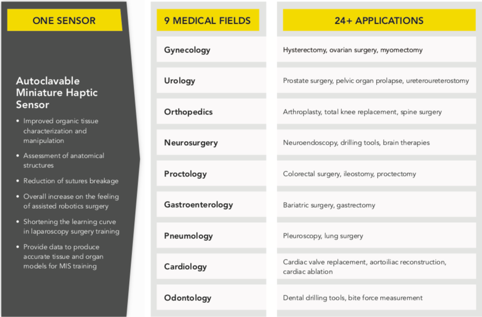
Direct benefits of sensing interaction forces at the surgical end-effector are:

  • Improved organic tissue characterization and manipulation
  • Assessment of anatomical structures
  • Reduction of sutures breakage
  • Overall increase on the feeling of assisted robotics surgery.

Haptic feedback also plays a fundamental role in shortening the learning curve for young surgeons in MIRS training. A tertiary benefit of accurate real-time direct force measurement is that the data collected from these sensors can be utilized to produce accurate tissue and organ models for surgical simulators used in MIS training. Futek Advanced Sensor Technology, an Irvine, Calif.-based sensor manufacturer, shared these tips on how to design and manufacture haptic sensors for surgical robotics platforms.

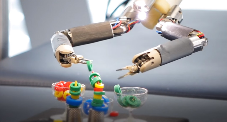
With a force, torque and pressure sensor enabling haptic feedback to the hands of the surgeon, robotic minimally invasive surgery can be performed with higher accuracy and dexterity while minimizing trauma to the patient. | Credit: Futek

Technical and economic challenges of haptic feedback

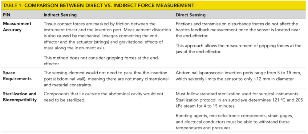
Adding to the inherent complexity of measuring haptics, engineers and neuroscientists also face important issues that require consideration prior to the sensor design and manufacturing stages. The location of the sensing element, which significantly influences the measurement consistency, presents MIRS designers with a dilemma: should they place the sensor outside the abdomen wall near the actuation mechanism driving the end-effector (a.k.a. Indirect Force Sensing), or inside the patient at the instrument tip, embedded on the end-effector (a.k.a. Direct Force Sensing).

The pros and cons of these two approaches are associated with measurement accuracy, size restrictions and sterilization and biocompatibility requirements. Table 1 compares these two force measurement methods.

In the MIRS applications, where very delicate instrument-tissue interaction forces need to give precise feedback to the surgeon, measurement accuracy is sine qua non, which makes intra-abdominal direct sensing the ideal option.

However, this novel approach not only brings the design and manufacturing challenges described in Table 1 but also demands higher reusability. Commercially available MIRS systems that are modular in design allow the laparoscopic instrument to be reutilized approximately 12 to 20 times. Adding the sensing element near to the end-effector invariably increases the cost of the instrument and demands further consideration during the design stage in order to enhance sensor reusability.

Appropriate electronic components, strain measurement method and electrical connections have to withstand additional autoclavable cycles as well as survive a high PH washing. Coping with these special design requirements invariably increases the unitary cost per sensor. However, extended lifespan and number of cycles consequently reduces the cost per cycle and brings financial affordability to direct measurement method.

Hermeticity of high precision sub-miniature load sensing elements is equally challenging to intra-abdominal direct force measurement. The conventional approach to sealing electronic components is the adoption of conformal coatings, which are extensively used in submersible devices. As much as this solution provides protection in low-pressure water submersion environments for consumer electronics, coating protection is not sufficiently airtight and is not suitable for high-reliability medical, reusable and sterilizable solutions.

Under extreme process controls, conformal coatings have shown to be marginal and provide upwards of 20 to 30 autoclave cycles. The autoclave sterilization process presents a harsher physicochemical environment using high pressure and high temperature saturated steam. Similar to helium leak detection technology, saturated steam particles are much smaller in size compared to water particles and are capable of penetrating and degrading the coating over time causing the device to fail in a hardly predictable manner.

An alternative and conventional approach to achieving hermeticity is to weld on a header interface to the sensor. Again, welding faces obstacles in miniaturized sensors due to its size constraints. All in all, a novel and robust approach is a monolithic sensor using custom formulated, Ct matched, chemically neutral, high temperature fused isolator technology used to feed electrical conductors through the walls of the hermetically sealed active sensing element. The fused isolator technology has shown reliability in the hundreds to thousands of autoclave cycles.


The Robot Report launched the Healthcare Robotics Engineering Forum (Dec. 9-10 in Santa Clara, Calif.). The conference and expo focuses on improving the design, development and manufacture of next-generation healthcare robots. The Healthcare Robotics Engineering Forum is currently accepting speaking proposals through July 26, 2019. To submit a proposal, fill out this form.


Other design considerations for haptic feedback

As aforementioned, miniaturization, biocompatibility, autoclavability and high reusability are some of the unique characteristics imposed to a haptic sensor by the surgical environment. In addition, it is imperative that designers also meet requirements that are inherent to any high-performance force measurement device.

Extraneous loads (or crosstalk) compensation, provides optimal resistance to off-axis loads to assure maximum operating life and minimize reading errors. Force and torque sensors are engineered to capture forces along the Cartesian axes, typically X, Y and Z. From these three orthogonal axes, one to six measurement channels derives three force channels (Fx, Fy and Fz) and three torque or moment channels (Mx, My and Mz). Theoretically, a load applied along one of the axes should not produce a measurement in any of the other channels, but this is not always the case. For a majority of force sensors, this undesired cross-channel interference will be between 1 and 5% and, considering that one channel can capture extraneous loads from five other channels, the total crosstalk could be as high as 5 to 25%.

In robotic surgery, the sensor must be designed to negate the extraneous or cross-talk loads, which include frictions between the end-effector instrument and trocar, reactionary forces from the abdominal wall and gravitational effect of mass along the instrument axis. In some occasions, miniaturized sensors are very limited in space and have to compensate side loads using alternate methods such as electronic or algorithmic compensation.

haptic sensorsCalibration of direct inline force sensor imposes restrictions as well. The calibration fixtures are optimized with SR buttons to direct load precisely through the sensor of the part. If the calibration assembly is not equipped with such arrangements, the final calibration might be affected by parallel load paths.

Thermal effect is also a major challenge in strain measurement. Temperature variations cause material expansion, gage factor coefficient variation and other undesirable effects on the measurement result. For this reason, temperature compensation is paramount to ensure accuracy and long-term stability even when exposed to severe ambient temperature oscillations.

The measures to counteract temperature effects on the readings are:

  • The use of high-quality, custom and self-compensated strain gages compatible with the thermal expansion coefficient of the sensing element material
  • Use of half or full Wheatstone bridge circuit configuration installed in both load directions (tension and compression) to correct for temperature drift
  • Fully internally temperature compensation of zero balance and output range without the necessity of external conditioning circuitry.

In some special cases, the use of custom strain gages with reduced solder connections helps reduce temperature impacts from solder joints. Usually, a regular force sensor with four individual strain gages has upwards of 16 solder joints, while custom strain elements can reduce this down to less than six. This design consideration improves reliability as the solder joint, as an opportunity for failure, is significantly reduced.

During the design phase, it is also imperative to consider such sensors to meet high reliability along with high-volume manufacturability, taking into consideration the equipment and processes that will be required should a device be designated for high-volume manufacturing. The automated, high-volume processes could be slightly or significantly different than the benchtop or prototype equipment used for producing lower volumes. The scalability must maintain focus on reducing failure points during the manufacturing process, along with failure points that could occur on the field.

Testing for medical applications is more related to the ability of a measurement device that can withstand a high number of cycles rather than resist to strenuous structural stress. In particular for medical sensors, the overload and fatigue testing must be performed in conjunction with the sterilization testing in an intercalated process with several cycles of fatigue and sterilization testing. The ability to survive hundreds of overload cycles while maintaining hermeticity translates into a failure-free, high- reliability sensor with lower MTBF and more competitive total cost of ownership.

haptic sensors

Credit: Futek

Product development challenges

Although understanding the inherent design challenges of the haptic autoclavable sensor is imperative, the sensor manufacturer must be equipped with a talented multidisciplinary engineering team, in-house manufacturing capabilities supported by fully developed quality processes and product/project management proficiency to handle the complex, resource-limited, and fast-paced new product development environment.

A multidisciplinary approach will result in a sensor element that meets the specifications in terms of nonlinearity, hysteresis, repeatability and cross-talk, as well as an electronic instrument that delivers analog and digital output, high sampling rate and bandwidth, high noise-free resolution and low power consumption, both equally necessary for a reliable turnkey haptics measurement solution.

Strategic control of all manufacturing processes (machining, lamination, wiring, calibration), allows manufacturers to engineer sensors with a design for manufacturability (DFM) mentality. This strategic control of manufacturing boils down to methodically selecting the bill of material, defining the testing plans, complying with standards and protocols and ultimately strategizing the manufacturing phase based on economic constraints.

The post Challenges of building haptic feedback for surgical robots appeared first on The Robot Report.

MiR500 mobile robot helps Cabka automate pallet transport


Germany-based Cabka Group recycles post-industrial plastics into pallets and other material handling products. Cabka North America’ 400,000-square-foot plant in the St. Louis, Missouri area runs 24/7 to manufacture about 5,000 pallets per day.

But Cabka is challenged by labor shortages due to high turnover of temporary workers, which leads to expensive downtime. At Cabka North America’s facility, workers at eleven injection molding machines unload plastic pallets and manually trim and stack them for material handlers to transport to the warehouse using fork trucks or pallet jacks. The work is repetitive and physical, making it hard to retain workers, and the presence of fork trucks on the production floor leads to safety concerns.

However, a new, fully automated production line that will be replicated throughout the facility is helping minimize dependency on temporary workers while also improving product quality and worker safety.

A Mobile Industrial Robots MiR500 autonomous mobile robot is part of that fully automated production line. The production line also includes a Krauss Maffei six-axis robot to autonomously unload pallets from the injection molding machine, trim the pallets, and load the finished products directly onto the MiR500. The MiR500, which is equipped with a MiR pallet lift, transports the finished products out of the manufacturing floor to a separate staging area as soon as the job is complete.

In the staging area, the pallets can be checked for quality and wrapped. Fork trucks then transport the finished pallets to the warehouse and loading docks without having manufacturing workers present. This will allow Cabka to eliminate fork truck traffic in the production area, replacing them with safe, collaborative mobile robots.

MiR500

Cabka North America uses a MiR500 autonomous mobile robot to transport plastic pallets. | Credit: Mobile Industrial Robots

Pilot project leads to fully optimized production

The fully automated production line is intended to be the model for the eventual automation of all eleven production lines, with a fleet of MiR robots supporting them in a dynamic, highly efficient manufacturing floor. Each AMR can go where it’s needed when it’s needed to keep production flowing.

Cabka estimates the first MiR500 travels about three miles a day supporting one production line. With eleven lines planned for autonomous material transport with multiple MiR robots, workers and fork truck drivers will be relieved from many miles of manual material handling, allowing Cabka to redeploy those workers to higher-value tasks.

“With the MiR500, we are very happy with the payload,” said Cabka project technician Craig Bossler. “It’s handled everything that we can stack on top of it. We haven’t found out how high we can go yet. It’s very stable — it can make turns, go straight, and it can hit bumps, and it’s always very stable. The MiR definitely can handle all the imperfections in the floor.”

MiR500

Production of MiR5000 autonomous mobile robots. The company says 40 percent of its sales has gone to the U.S. | Credit: Mobile Industrial Robots

Adding more MiR500 mobile robots

Cabka North America is looking at other ways to use the MiR robots, including prepping orders overnight in the warehouse so they will be ready at the dock for loading in the morning. Patrick Garin, president of Cabka North America, anticipates that other Cabka locations will be following the North American facility’s lead.

“We always have our corporate people come here – our corporate CEO and the other part of the team – and they will definitely be very interested in seeing our progress here,” he said.

Teradyne Inc. of North Reading, Mass., recently acquired Mobile Industrial Robots of Odense, Denmark. Three years ago, Teradyne also purchased another Danish automation company, collaborative robot maker Universal Robots.

The post MiR500 mobile robot helps Cabka automate pallet transport appeared first on The Robot Report.

Toolcraft turns to UR e-Series cobots to save on production, increase throughput

Toolcraft Inc., a small precision machining shop in Seattle, makes parts for industries including aerospace, defense, and medical. It needed help tending its CNC machine and ultimately turned to Universal Robots A/S’s e-Series collaborative robots.

Faced with labor shortages and a demanding manufacturing task, Toolcraft assessed its alternatives and worked with an integrator to apply a UR5e cobot to its process.

Challenge

Toolcraft needed to automate a three-step task to keep up with production demands, especially when a large medical device required it to add a third shift for round-the-clock operations. Finding workers is difficult in a region with 3% unemployment.

UR5e Toolcraft case study

“Nobody wants to run on third shift around here,” said Steve Wittenberg, director of operations at Toolcraft. “When you put an ad out, you’re not getting very many responses.”

The company initially looked at traditional industrial robots but realized that it would have to add costly safety infrastructure.

“If we looked at just the robot hardware alone, that appeared to be a more cost-effective solution,” Wittenberg said. “But once we started factoring in the savings on not having to erect a safety cage – and the time saved on the ease of use, avoiding a lot of complex programming – Universal Robots ended up being the right solution.”

Solution

Toolcraft discussed its need for loading a medical device part into a CNC machine for multi-threading with Rapid Design Solutions, a certified systems integrator for UR cobots.

“When we heard that the repeatability of the UR5e was down to 30 microns, we were very excited,” said Troy Ojalehto, owner of Rapid Design Solutions. “That really competes in the same space as traditional industrial robots, so that was huge for us. I have not seen other cobots handling this level of precision with multi-op parts like this, with raw stock going in and completed precision parts coming out.”

Thanks to its force-feedback feature, the UR5e is able to make the part fit tightly in the CNC fixturing. “Using the force motion with freedom in the X,Y and rotational Z axes, we can force the part in there, and wiggle it, and program that compliance very easily to enable basically a human touch with the robot,” he said.

The UR+ program, which certifies that accessories such as grippers, vision systems, and software will work with UR cobots, helped speed up integration.

“For this application, we chose a Pneu-Connect pneumatic gripper,” said Ojalehtos. “A big factor is that it’s UR+ certified, which means it works with Universal right out of the box, with all gripper software integrated directly on the UR teach pendant, eliminating the need to do any script coding.”

PneuConnect gripper at Toolcraft

Toolcraft chose the UR+ certified PneuConnect gripper, which works seamlessly with UR’s teach pendant. Source: Universal Robotics

Results at Toolcraft

“Some of the benefits we’ve seen right off were a significant production increase,” said Wittenberg. “We were able to staff that third shift and went from producing 255 parts a week to 370 parts per week. Along with that, we’re able to finish our year’s production seven weeks sooner, thus freeing up that machine to produce parts on other jobs.”

After six months, Toolcraft saw costs decline by 23%, and it now expects a return on investment on the cobot arm at about 12 months.

“We’re going to be able to be more competitive on a lot of the long-term work that we have,” Wittenberg said.

Since the UR5e cobot only tends parts for six minutes out of a 56-minute cycle, a Toolcraft engineer added a part rinsing and cleaning station after using Universal Robots‘ online training.

“After our automation engineer took the online UR Academy, he spent a few hours with the integrator and was able to add that station to the cobot cycle with no external help otherwise,” said Wittenberg. Universal Robots’ simulator also allowed Toolcraft to program most of the additional tasks without taking the cobot offline.

Toolcraft worked with integratos

After certified systems integrator Troy Ojalehto (right) developed the initial application, Toolcraft automation engineer Brian Laulainen (left) was able to handle daily operations and build add-ons for the UR5e after training through the UR Academy. Source: Universal Robots

In addition, the company was easily able to use Universal Robots‘ I/O interfaces to control the pneumatic fixture and door actuators. “This greatly reduces the need for CNC wiring and preserves all the CNC’s standard safety functions,” Ojalehto said.

The installation has been so successful that Toolcraft is planning to install one cobot every year. “The fact that our own automation engineer is now able to go in and troubleshoot anything that comes up is going to be key in us meeting this goal,” Wittenberg said.

Toolcraft plans to automate tending a horizontal mill next. “That’s a potential challenge because of the mills using rotary tombstones that are swapped in and out of the milling machine, which creates some difficulties with fixturing,” said Wittenberg. “But we’re confident we can solve those using a Universal Robot and some innovation in fixturing.”

The post Toolcraft turns to UR e-Series cobots to save on production, increase throughput appeared first on The Robot Report.